High Country Tek, Inc. Hydraulic Generator Controller – HGC-2 Electronic Controller Solutions for Mobile, Industrial & Marine Applications. Application Guide, Set-up & Information Manual. Manual Part No.
Hydraulic Generator Controller – HGC-2 Important Notes: This product has been designed to interface directly with any manufacturers range of proportional pressure and/or flow control valves, variable pumps, motors and manifold blocks currently available. Please contact the factory by the e-mail address given below or nearest High Country Tek, Inc. distributor for further technical information and availability. Application Limitations: High Country Tek, Inc.
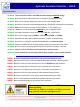
Hydraulic Generator Controller – HGC-2 Important Notes: ALWAYS - Take a few minutes to FULLY read THESE information / data sheets BEFORE starting. ALWAYS - Keep High Voltage AC cables separate from Low Voltage DC signal and supply cables. ALWAYS - Make sure the unit supply voltage is the same as the coils on the valve being driven ! ALWAYS - Ensure that you are aware of the available adjustments and consequences on the electronics and hydraulics.
Hydraulic Generator Controller – HGC-2 Product Features: Digital controller for repeatability, reliability and accuracy in your application Accuracy is dependent on HGC-2 module ‘Tuning’ and the type of hydraulic circuit used 100 to 250VRMS generator output compatible 50 or 60 Hz settable for global sales opportunities ( trimmable frequency to +/-3Hz in 0.1Hz increments ) User configurable Under and Over frequency handling. Wide supply voltage 9 to 28VDC and full reverse polarity protection.
Hydraulic Generator Controller – HGC-2 Software and PC requirements Min Requirements, Disk space: 165MB (Software, GUI and National Instruments embedded drivers required). Physical Memory: 2.5MB Screen Resolution: 1024X768 Important Note: • The unit is supplied with 3 default .dat files for the 3 current HGC-2 module versions available from HCT. • If ‘On-line’ with the controller, only open the .dat file for your current model.
Hydraulic Generator Controller – HGC-2 About the HGC-2 Controller: The HGC-2 Hydraulic Generator Controller is the latest addition to the HCT family of rugged controller modules, designed for reliability under extreme conditions. The highly cost effective HGC-2 is designed to control a generator driven by a hydraulic motor where speed is controlled by a proportional solenoid valve, either directly at the motor or as part of the pump compensator.
Hydraulic Generator Controller – HGC-2 Loading the HGC-2 GUI onto your PC: Go to www.hctcontrols.com or contact HCT customer service on 1 530 265 3236 to ensure you have the latest revision of the HGC-2 Graphical User Interface (GUI ) The PC Graphical User Interface ( GUI ) is a self extracting and installing program that will reside on the chosen host PC hard drive.
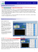
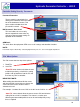
Hydraulic Generator Controller – HGC-2 Explanation of major windows: 1 1. The header of the GUI window tells the user the type/art number of the controller that is connected to the host PC. 2. This main indicator should be bright GREEN to show a correct operational function of the controller, with the light showing real-time status of the units operation. If there is an error of any type, this indicator will be bright RED with the fault description shown under the light until the fault is cleared. 3.
Hydraulic Generator Controller – HGC-2 ‘Help’ Menu Options: The ‘Help’ menus has two drop down options: 1. Print Parameters 2. View Help. 3. About Controller. ‘Print Parameters’ when clicked, this option will allow the user to get a hard copy of the controller settings via the default printer connected to the PC ‘View Help’ when clicked, will open a PDF format file that is the complete manual for the HGC-2 controller, allowing local on-site information support for the user.
Hydraulic Generator Controller – HGC-2 Controller Setting Security - Passwords: Password Protection: The password is entered after first clicking the ‘Password’ tab on the index bar of the ‘dashboard’ screen, This opens another window where the password is entered. NO Password – User Level: This level allows the user to only observe operation but not make any changes to the parameter settings or operation of the controller.
Hydraulic Generator Controller – HGC-2 ‘Unit’ Menu Options: The ‘Unit’ menus has three drop down options: File Help Password Quit 1. Read Parameters. 2. Send parameters. 3. Find Controller. ‘Read Parameters’ Selecting this option allows the GUI to read the parameter setting file from a connected controller to allow backup, editing or copying to other controllers.
Hydraulic Generator Controller – HGC-2 ‘Data Logging’ Options: The HGC-2 controller can log operational data as long as it is connected to the host PC. The data is directly saved onto the PC hard drive as a CSV format file, into a location that can be selected by the user. Logging is started by the user clicking the ‘Log Data’ button The controller logs the following data: 1. Valve coil Current 2. PSU voltage 3.
Hydraulic Generator Controller – HGC-2 ‘Fault’ Screens: SHORT CIRCUIT FAULT DETECTED: This fault is displayed when the controller detects that the proportional coil or wires being attached to the PWM output have become short circuit or have failed internally to a short-circuit condition. Other causes of this fault detection may be shorted wires to the valve or within the generator set enclosure. If this fault is triggered, the HGC-2 PWM output will be set to zero output ( i.e.
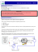
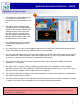
Hydraulic Generator Controller – HGC-2 Connecting the HGC-2 to the Programming Cable: In order for the HGC-2 to communicate with the PC User Interface, a programming cable ( 999-10166) must be temporarily connected to the PC USB port and also to the HGC-2 controller. The controller and programming cable use Infra-red transmission technology for fast data transfer and the user must ensure that the programming head is correctly aligned and fitted to the controller for successful communications.
Hydraulic Generator Controller – HGC-2 HGC-2 Controller Settings and Descriptions: TARGET FREQUENCY - The Target Frequency parameter sets the desired output frequency of the generator to 50Hz or 60Hz. The Proportional parameter is a variable type. PROPORTIONAL GAIN. - The Proportional parameter sets the proportional gain in the control loop. The proportional gain represents the P term in a PID control loop. The proportional term is simply a multiplication of the error which is added to the output.
Hydraulic Generator Controller – HGC-2 HGC-2 Controller Settings and Descriptions: MAXIMUM OUTPUT - The Maximum Output parameter represents the maximum current of the output. This is often referred to as the gain. The value displayed represents the current in milliamps (amps for -12A, -25A). The Maximum Output parameter is variable. MINIMUM FREQ - The Minimum Frequency parameter is used to establish the minimum frequency for the desired range of operation.
Hydraulic Generator Controller – HGC-2 Initial Set-up Procedure: The following steps are recommended when commissioning a HGC-2 controller: 1. Select the desired operating frequency. 2. Set the Minimum and Maximum Output currents according to the valve data sheet. 3. Set the Dither Frequency as recommended by the valve manufacturer. ( NOTE: Higher dither frequencies can sometimes be used in closed loop systems to improve frequency response). 4.
Hydraulic Generator Controller – HGC-2 Operational Guide: The following section gives the user a generic overview of expected control results once the controllers PID settings have been optimized for the individual generator set-up being produced.
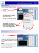
Hydraulic Generator Controller – HGC-2 Operational Guide – DC Supply Voltage Fluctuation: DC Supply Voltage Fluctuation 13V – 10V – 13V within 1 second 80 Frequency - Hz 75 The HGC-2 has been designed to work under extreme conditions seen in mobile equipment.
Hydraulic Generator Controller – HGC-2 HGC-2 Electrical Specification: 1. Housing Type:- HCT unique ‘encapsulated’ block. 2. Input Supply Voltage: +9 to +28VDC ( Absolute Maximum ) 3. Input Supply Current: Valve Current Setting + 50mA Quiescent (Max) 4. **Feedback Voltage:- 100 to 250VRMS ( See note below in yellow box ) 5. O/P Current Ranges:- 600mA, 1.2A or 2.5A ( specified at time of order ) 6. Solenoid Min Ohms:- 2Ω minimum resistance 7.
Hydraulic Generator Controller – HGC-2 HGC-2 Error code Description (STATUS): Blink OFF Definition System is OK and operating normally 2 Open Circuit On Controller Output – wires to solenoid disconnected while under power 3 Short Circuit On Controller Output - wires or solenoid have become short circuited 5 Frequency Fault – output frequency has been below min. or above max.
Hydraulic Generator Controller – HGC-2 Electrical System Connections: Pin Function 1 +VDC Input Supply 2 0VDC Input Supply 3 +Solenoid Connection O/P 4 -Solenoid Connection O/P 5 AC feedback Neutral I/P 6 AC feedback Line I/P 7 Constant Current Mode enable I/P 8 Controller ENABLE I/P Beware of HIGH VOLTAGE when operating any generator system – high voltage can be LETHAL – observe ALL laws, by-laws and health & Safety recommendations for your immediate location, state and/or country.
Hydraulic Generator Controller – HGC-2 HGC-2 Ordering Information: H G C 2 - 1 2 Output Current Range: 06 - 600mA current range 12 - 1200mA current range 25 - 2500mA current range Notes: •The current range chosen represents the maximum current available at the controller output. • See rear of controller for part number and model number HGC-2 Connector Kit: 8 way Metri-Pack 150 series MALE connector Note:Mating connector gender:- 8 way Female ( Socket ) kit complete with pins and separator.
Hydraulic Generator Controller – HGC-2 Mining & Exploration Agriculture Cranes & lifts Refuse & Recycling Construction Off-Road vehicles Forestry, Wood & Pulp Reclamation & Salvage Oil Field & Sands Demolition Equipment Cooling Solutions Military Apparatus Specialty Use Remote Control Power Generation Emission Controls Integrated Drivers Valve & Pump Controls HCT Product Sales and Support: For a full list of authorized distributors worldwide, please visit: www.