Electronic Controller Solutions for the Global Fluid Power Industry High Country Tek,Hydraulic Inc. Fan System Controller with SAE J1939 Interface HFS-J User Guide Hydraulic Fan Drive User Guide: HFS-J Electronic Control Solutions for the Global Fluid Power Industry HFS-J Hydraulic Fan Drive System Controller User Guide High Country Tek, Inc. reserves the right to improve this product at any time and without notice. This manual may contain mistakes and printing errors.
Electronic Controller Solutions for the Global Fluid Power Industry Hydraulic Fan System Controller with SAE J1939 Interface HFS-J User Guide High Country Tek, Inc. (HCT) is North America’s foremost independent designer and producer of modular, ruggedized digital and analog electronic controller products for the fluid power industry.
Electronic Controller Solutions for the Global Fluid Power Industry Hydraulic Fan System Controller with SAE J1939 Interface HFS-J User Guide Manual Index: Introduction: ....................................................................................................................... 4 Cautions: ............................................................................................................................. 4 Warranty Information: ..........................................................
Electronic Controller Solutions for the Global Fluid Power Industry Hydraulic Fan System Controller with SAE J1939 Interface HFS-J User Guide Welcome to the High Country Tek Inc. ( HCT ) HFS-J Hydraulic Fan Drive system controller user guide, and thank you for selecting this HCT controller to use in your application. The following information is designed to allow you to connect, set-up and optimize the HFS-J module.
Electronic Controller Solutions for the Global Fluid Power Industry Hydraulic Fan System Controller with SAE J1939 Interface HFS-J User Guide ‘HFS-J’ Hydraulic Fan System Controller: The HFS-J is the latest addition to the High Country Tek ( HCT ) family of hydraulic fan control modules. The highly cost effective HFS-J has enough processing power and input output functionality when operating as a single control module to support a wide range of hydraulic fan system applications.
Electronic Controller Solutions for the Global Fluid Power Industry Hydraulic Fan System Controller with SAE J1939 Interface HFS-J User Guide Product Overview • NO software experience needed to apply this controller successfully. • Pre-written ‘Fan Drive’ software for easy, fast system configuration, development and production. • Intuitive Graphical User Interface ( GUI ) runs on any PC with Windows® XP or newer software ( .net compatible ).
Electronic Controller Solutions for the Global Fluid Power Industry Hydraulic Fan System Controller with SAE J1939 Interface HFS-J User Guide Product Application Guidelines: ALWAYS do the following: • • • • • • • • • • • • • • Take a few minutes to FULLY read THESE information / data sheets BEFORE starting. Keep High Voltage AC cables separate from Low Voltage DC signal and supply cables.
Electronic Controller Solutions for the Global Fluid Power Industry Hydraulic Fan System Controller with SAE J1939 Interface HFS-J User Guide Module Familiarity: Controller ‘STATUS’ led – Bi-color, indicates what the module is doing at any given time.
Electronic Controller Solutions for the Global Fluid Power Industry Hydraulic Fan System Controller with SAE J1939 Interface HFS-J User Guide Electrical Specification Overview: 1) Board Style: High Country Tek unique size and mounting. 2) Connector Type: 3) Comms. I/O connector: 4) Comms. Type: 12 way male Deutsch DT series 4 way Packard MALE ( Tower ) connector on 6 inch, 4 core umbilical cable. Serial data at 57.6K Baud through PC USB/Serial port.
Electronic Controller Solutions for the Global Fluid Power Industry Hydraulic Fan System Controller with SAE J1939 Interface HFS-J User Guide Application Examples: NOTE:Controller MUST have in-line fuse fitted by user in +V Power Input for system protection. NOTE:View looking at 12 way male connector on HFS - J controller - DTF15-12PB Pin 1:Pin 2:Pin 3:Pin 4:Pin 5:Pin 6:Pin 7:Pin 8:Pin 9:Pin 10:Pin 11:Pin 12:- Thermistor #1 +signal input. Thermistor #2 +signal input.
Electronic Controller Solutions for the Global Fluid Power Industry Hydraulic Fan System Controller with SAE J1939 Interface HFS-J User Guide Error LED code descriptions: Status LED OFF OFF ON ON ON ON ON ON Code = 1 Code = 2 Code = 3 Code = 1 Code = 2 Code = 3 Code = 5 Code = 1 Code = 3 Code = 4 Code = 5 Code = 6 Code = 7 Code = 8 NOTES: 1 2 3 4 5 6 7 8 Reverse / Error LED OFF OFF OFF OFF OFF Flashing Flashing Flashing Flashing Flashing Flashing Flashing Flashing Flashing Flashing Flashing Flashing Flas
Electronic Controller Solutions for the Global Fluid Power Industry Hydraulic Fan System Controller with SAE J1939 Interface HFS-J User Guide Module Connection Descriptor: Thermistor #1 Input ( Connector terminal 1 ): This input is designed to accept a standard NTC thermistor OR a bi-metallic temperature switch. This input should be used in conjunction with the 0V pin # 8 on the connector; the choice is made via the GUI.
Electronic Controller Solutions for the Global Fluid Power Industry Hydraulic Fan System Controller with SAE J1939 Interface HFS-J User Guide Signal Common Input ( Connector terminal 8 ): This input should be used in conjunction with the thermistor input # 1and is internally connected to Power Common ( Terminal 7 ) on the card. To provide the best possible noise resistance Sig Com should be used as the only ground for the temperature sensors.
Electronic Controller Solutions for the Global Fluid Power Industry Hydraulic Fan System Controller with SAE J1939 Interface HFS-J User Guide Serial Communications: HFS-J monitoring, health checks, diagnostics and set-up can be accessed through the supplied GUI. This program will operate on PC using a based Windows® operating system and is password protected to maintain module parameter integrity by only allowing authorized users to access different levels of the controller settings.
Electronic Controller Solutions for the Global Fluid Power Industry Hydraulic Fan System Controller with SAE J1939 Interface HFS-J User Guide Loading the HFS-J GUI onto Host PC: The PC Graphical User Interface ( GUI ) is a self extracting and installing program that will reside on the chosen host PC hard drive. It is recommended that the user allow the defaults to be used for easy future update installation, but the option is given to allow the user to choose where the program should be located.
Electronic Controller Solutions for the Global Fluid Power Industry Hydraulic Fan System Controller with SAE J1939 Interface HFS-J User Guide File ( Memory Options ): -> Load and Save settings to file The user has two simple options available: 1) Load settings from file. This option allows the user to search for and find preciously saved settings files ( *.DAT ) and to load them into a new controller or to reset a controller to a previous version e.t.c. 2) Save settings to file.
Electronic Controller Solutions for the Global Fluid Power Industry Hydraulic Fan System Controller with SAE J1939 Interface HFS-J User Guide Password Protection Passwords will be asked for when the user attempts to enter a mode that requires authorization. Once the password has been entered once during a session it will not be requested again unless a higher level password is needed to proceed to an advanced option outside the current access level.
Electronic Controller Solutions for the Global Fluid Power Industry Hydraulic Fan System Controller with SAE J1939 Interface HFS-J User Guide Help: When this menu is selected, a drop down menu displays two options:1) HFS-J ‘Help’: This option calls and opens a PDF file that is part of the installation package. The help file contains useful information on application, set-up and diagnostics.
Electronic Controller Solutions for the Global Fluid Power Industry Hydraulic Fan System Controller with SAE J1939 Interface HFS-J User Guide GUI software – Main screen (Dashboard) The software has been designed such that there is NO nesting of menus so that it is easy to navigate around the different screens without getting lost or having multiple windows open at any one time.
Electronic Controller Solutions for the Global Fluid Power Industry Hydraulic Fan System Controller with SAE J1939 Interface HFS-J User Guide Controller Set-up: Selection Tab -> Settings This page gives the user access to all of the modules operational settings. • Valve Mode: Select Proportional OR ON/OFF valve type.
Electronic Controller Solutions for the Global Fluid Power Industry Hydraulic Fan System Controller with SAE J1939 Interface HFS-J User Guide Controller Set-up Cont: • PWM Freq ( Hz): This is the ‘dither’ frequency that will be applied to the fan speed control valve and should be selected to suit the manufacturers data for the valve type and size selected for the system.
Electronic Controller Solutions for the Global Fluid Power Industry Hydraulic Fan System Controller with SAE J1939 Interface HFS-J User Guide Controller Set-up Cont: • Temperature settings: There are up to five ( 5 ) temperature inputs into the HFS-J that can be individually enabled or disabled as required, three ( 3 ) come directly from the J1939 Bus, and are : Engine coolant at PGN 65262, Transmission Oil temperature at PGN 65272 and Intake manifold Temperature at PGN 65270 and do not need any ext
Electronic Controller Solutions for the Global Fluid Power Industry Hydraulic Fan System Controller with SAE J1939 Interface HFS-J User Guide Channel controlling fan speed: 140F 80F= Current Temp. 130F 120F 110F Fan Max Temp 120F Fan Max Temp 110F 100F 90F 130F Fan Max Temp Channel 3 Channel 1 80F Channel 2 70F 60F 50F Fan Start Temp 50F 40F 30F 20F 10F Controlling = 100 x Channel Fan Start Temp. 60F Fan Start Temp 40F Current Temp. – Fan Start temp. Fan Max Temp. – Fan Start temp.
Electronic Controller Solutions for the Global Fluid Power Industry Hydraulic Fan System Controller with SAE J1939 Interface HFS-J User Guide Error Information Log: Selection Tab -> Trouble Codes This page shows the user information that will help to track and where necessary, fix intermittent opens and short circuits on any of the wires used to connect to the sensors, switches or the coils in the system. The program shows where the error has been seen, even if the error has cleared itself.
Electronic Controller Solutions for the Global Fluid Power Industry Hydraulic Fan System Controller with SAE J1939 Interface HFS-J User Guide Data Logging: Selection Tab -> Data Log This page allows the user access to a data logger feature that will operate only when a PC running the GUI is connected and available to the controller. The Data logger will record several key pieces of information that can be used as a data point after commissioning or sent as a file to help with remote fault diagnosis.
Electronic Controller Solutions for the Global Fluid Power Industry Hydraulic Fan System Controller with SAE J1939 Interface HFS-J User Guide The logger will store the following data parameters: • • • • • • • • • Log Counter Number Module Input Voltage Module Internal Temperature Proportional Valve Current Thermistor #1 Temp I/P ( Actual ) Thermistor #2 Temp I/P ( Actual ) J1939 Coolant Temperature ( Actual ) J1939 Inlet Manifold Temperature ( Actual ) J1939 Transmission oil Temperature ( Actual ) Part N
Electronic Controller Solutions for the Global Fluid Power Industry Hydraulic Fan System Controller with SAE J1939 Interface HFS-J User Guide Miscellaneous Information: Selection Tab -> Misc This page allows the user to view information concerning the controller serial number, GUI Part number, BIOS and Graphical user Interface ( GUI ) software versions as well as the ‘Born Date’ which is taken from the local PC used to activate the module.
Electronic Controller Solutions for the Global Fluid Power Industry Hydraulic Fan System Controller with SAE J1939 Interface HFS-J User Guide Temperature Sensor Information: This information is intended as a guide only and should not be used for final system design or calculations. It is the users responsibility to check and confirm Latest information, accuracy, part Numbers And component availability.
Electronic Controller Solutions for the Global Fluid Power Industry Hydraulic Fan System Controller with SAE J1939 Interface HFS-J User Guide On Site Testing: If the set up procedure does not achieve the desired results, double check the wiring and perform the following tests. Record the test results.
Electronic Controller Solutions for the Global Fluid Power Industry Hydraulic Fan System Controller with SAE J1939 Interface HFS-J User Guide Valve not being driven to maximum: Note 1: Ohms Law says that when a coil heats up in use, it increases Ohmic resistance which de-creases the current flow. Most manufacturers coils, even when hot should still are able to fully shift the valve 100% if their rated voltage is supplied to them.
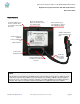
Electronic Controller Solutions for the Global Fluid Power Industry Hydraulic Fan System Controller with SAE J1939 Interface HFS-J User Guide HFS-J Dimensional Information: Notes: • • • • Unit weight is approx. 250 grams RS232 cable removed for clarity RS232 cable is approx 6” long Not to scale, please contact HCT for exact dimensions Housing Type:- High Country Tek unique ‘encapsulated’ block. Housing Material:- None, solid, flameproof epoxy resin block. Housing Color:- Black / dark Grey.
Electronic Controller Solutions for the Global Fluid Power Industry Hydraulic Fan System Controller with SAE J1939 Interface HFS-J User Guide Part No:- 021-00158 Rev C HFS-J Hydraulic Fan System Controller User Guide Page | 32
Electronic Controller Solutions for the Global Fluid Power Industry Hydraulic Fan System Controller with SAE J1939 Interface HFS-J User Guide Mining & Exploration Agriculture Cranes & lifts Refuse & Recycling Construction Off-Road vehicles Forestry, Wood & Pulp Reclamation & Salvage Oil Field & Sands Demolition Equipment Cooling Solutions Military Apparatus HCT Product Sales and Support: Specialty Use Remote Control Power Generation For a full list of authorized distributor