VERS 1.
ALLGEMEINE HINWEISE Aufgrund fortlaufender Weiterentwicklungen ist es möglich, dass die in diesem Benutzerhandbuch enthaltenen Hinweise und Informationen nicht vollständig dem Auslieferungszustand des Geräts entsprechen. LIEFERUMFANG 1 x TRX5005 DSP Verstärker 1 x Fernbedienung mit LED-Display inkl.
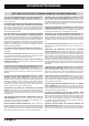
SICHERHEITSHINWEISE BITTE BEACHTEN SIE DIE FOLGENDEN HINWEISE VOR INBETRIEBNAHME! DAS VON IHNEN ERWORBENE GERÄT IST NUR FÜR DEN BETRIEB AN EINEM 12-V-BORDNETZ EINES FAHRZEUGS AUSGELEGT. Andernfalls besteht Feuergefahr, die Gefahr eines elektrischen Schlages oder anderer Verletzungen. BITTE KEINE BEDIENUNG DES SOUNDSYSTEMS AUSFÜHREN, WELCHE VOM SICHEREN LENKEN DES FAHRZEUGS ABLENKEN KÖNNTE. Führen Sie keine Bedienungen aus, die Ihre Aufmerksamkeit längere Zeit in Anspruch nehmen.
INSTALLATIONSHINWEISE HINWEIS Bevor Sie mit der Installation des Soundsystems beginnen, trennen Sie unbedingt den Massepol der Fahrzeugbatterie ab, um Kurzschlüsse und Stromschläge zu vermeiden. MECHANISCHE INSTALLATION Achten Sie bei der Installation darauf, dass keine serienmäßig im KFZ vorhandenen Teile wie z.B. Kabel, Bordcomputer, Sicherheitsgurte, Tank oder ähnliche Teile beschädigt bzw.entfernt werden. Vergewissern Sie sich, dass der Verstärker am Montageort genügend Kühlung erhält.
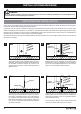
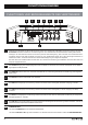
INSTALLATIONSHINWEISE ELEKTRISCHE ANSCHLÜSSE 1 2 3 4 5 VOR DEM ANSCHLIESSEN Für den fachgerechten Anschluss des Soundsystems sind geeignete Kabelsets im Fachhandel erhältlich. Achten Sie beim Kauf auf einen ausreichenden Kabelquerschnitt (mind. 25 mm2), den passenden Sicherungswert sowie auf die Leitfähigkeit der Kabel. Säubern und entfernen Sie vorhandene Rost- und Oxidationsstellen an allen Kontaktpunkten der Batterie und an den Massepunkten.
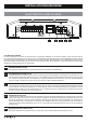
FUNKTIONSHINWEISE FUNKTIONEN UND BEDIENELEMENTE DES VERSTÄRKERS 2 1 1 3 4 5 6 7 8 9 Verbinden Sie bei Bedarf den Mini-USB-Anschluss mittels dem beiliegenden USB-Kabel mit Ihrem Computer, auf dem die M-CONTROL Software installiert ist. Die Verbindung kann nach dem Benutzen der DSP-Software wieder gelöst werden.
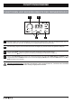
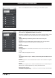
FUNKTIONSHINWEISE FUNKTIONEN UND BEDIENELEMENTE DER FERNBEDIENUNG 1 2 3 4 1 Mit diesem Regler kann die Gesamtlautstärke des Soundsystems geregelt werden. Wenn Sie den Regler drücken und ca. 3 Sekunden halten kann damit auch der Basspegel von Ausgang SUB OUT (G/H) geregelt werden. 2 Das LED-Display zeigt zum einen die Werte beim Drehen des Reglers (#1) oder die Nummer des gewählten Settings an. 3 Mit den beiden MODE-Tasten kann zwischen den im DSP gespeicherten Settings gewählt werden.
FUNKTIONSHINWEISE INSTALLATION DER DSP-SOFTWARE 1. Die DSP Software M-CONTROL 2 ist für alle Computer mit einem Windows™ Betriebssystem ab XP und einem USB-Anschluss geeignet. Die Installation benötigt ca. 25 MB freien Speicherplatz. Prinzipbedingt sollte dafür ein tragbarer Laptop-Computer verwendet werden. 2. Nachdem Sie die M-CONTROL 2 Software unter http://www.audiodesign.de/dsp heruntergeladen haben, entpacken Sie zunächst die heruntergeladene „.
FUNKTIONSHINWEISE Klicken Sie auf Click here to test um die Verbindung zum DSP-Gerät zu prüfen Wurde der Test erfolgreich durchgeführt erscheinen 4 Häkchen in den Checkboxen. Drücken Sie dann auf „[OK] Click here to start“ um fortzufahren. Sollte eines der Häkchen bei einer Checkbox nicht erscheinen, liegt ein Problem vor welches zu einer Fehlfunktion führen kann.
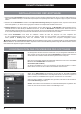
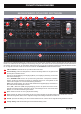
FUNKTIONSHINWEISE BEDIENOBERFLÄCHE DER SOFTWARE 10 1 3 8 4 5 6 2 9 17 7 16 11 13 12 14 15 Hier können Sie unzählige Einstellungen vornehmen und an Ihr Soundsystem anpassen, welche in Echtzeit über den DSP-Gerät sofort hörbar sind. Sobald Sie mit der Konfiguration eines Settings fertig sind, kann dieses auf den einen Speicherplatz im DSP-Gerät übertragen werden. Sie können bis zu 10 verschiedene Settings speichern und mit der Fernbedienung jederzeit im laufenden Betrieb auswählen.
FUNKTIONSHINWEISE 7 Unter „PRESETS ON THE DEVICE“, können Sie die Speicherplätze (POS1 - POS10) für die einzelnen Settings auf dem DSPGerät auslesen, löschen oder belegen. Wählen Sie zunächst den Speicherplatz (POS1 - POS10), denn Sie bearbeiten oder auslesen möchten aus. FUNKTIONSHINWEISE WRITE*: Speichert die augenblicklich eingestellte Einstellungen (Setting) im DSP-Gerät auf dem zuvor ausgewählten Speicherplatz ab. READ*: Liest den zuvor ausgewählten Speicherplatz aus dem Speicher des DSP-Gerät aus.
FUNKTIONSHINWEISE 16 Im Abschnitt „TIME ALIGNMENT“ finden Sie eine vereinfachte Möglichkeit, die Laufzeitkorrektur der einzelnen Kanäle von M-CONTROL 2 berechnen zu lassen, um das Soundsystem und das DSP-Gerät optimal auf die akustische Bühnenmitte auszurichten. Beachten Sie dazu die folgenden Schritte: • Messen Sie zuerst den Abstand aller Lautsprecher des Soundsystems zur akustischen Bühnenmitte (z.B. der Fahrersitz auf Ohrhöhe des Fahrers).
TECHNISCHE DATEN MODELL TRX5005DSP KANÄLE SCHALTUNGSPRINZIP 5 Kanal 1-4 CLASS A/B Analog Kanal 5 CLASS D Digital AUSGANGSLEISTUNG RMS 13,8 V Kanal 1-4, Watt an 4 / 2 Ohm Kanal 5 (Subwoofer) Watt an 4 / 2 / 1 Ohm 4 x 75 / 125 1 x 250 / 450 / 650 AUSGANGSLEISTUNG MAX.
FEHLERBEHEBUNG Fehler: keine Funktion Ursache: 1. Die Stromversorgungskabel sind nicht korrekt angeschlossen. 2. Die Kabel haben keinen elektrischen und mechanischen Kontakt. 3. Die Remote-Steuerleitung des Steuergeräts (Autoradio) ist nicht korrekt am Verstärker angeschlossen. 4. Sicherungen defekt. Im Falle des Austauschs achten Sie bitte auf den korrekten Wert der Sicherungen.
FEHLERBEHEBUNG Fehler: kein Ton vom Subwoofer Ursache: 1. Die Lautstärke des Subwoofer-Ausgangs (Kanal G/H bzw. SUB OUT) ist an der Fernbedienung zu leise eingestellt. Lösung: Regler der Fernbedienung drücken und halten, Lautstärke erhöhen wie auf Seite. 7 beschrieben. Fehler: „ERROR“-Meldung bei Verbindung zwischen DSP-Gerät und Computer Ursache: 1.
FEHLERBEHEBUNG STÖRUNGEN / INTERFERENZEN Die Ursache von Interferenzen sind meist immer die verlegten Kabel. Besonders anfällig dafür sind die Strom- und Cinchkabel des Sound Systems. Oftmals werden Interferenzen durch Generatoren (Lichtmaschine) oder andere elektronische Steuergeräte des KFZ (Benzinpumpe, Klimaanlage etc.) verursacht. Die meisten dieser Probleme können durch korrektes und sorgfältiges Verkabeln vermieden werden. Hier finden Sie dazu einige Hilfestellungen: 1.
NOTIZEN 17
GENERAL NOTES Due to the ongoing development of this device, it is possible that the information in this manual is incomplete or is not matching to the delivery status. SCOPE OF DELIVERY 1 x TRX5005 DSP Amplifier 1 x Remote Controller with LED Display, incl. Connection Cable 1 x USB Cable, A- to Mini-B Connector, 5 m 1 x CD-ROM with M-CONTROL Software 1 x Owner‘s Manual (German/English) 1 x Spare Fuse NOTE This symbol shows you important notes on the following pages.
SAFETY INSTRUCTIONS PLEASE NOTE THE FOLLOWING ADVICE BEFORE THE FIRST OPERATION! THE PURCHASED DEVICE IS ONLY SUITABLE FOR AN OPERATION WITH A 12V ON-BOARD ELECTRICAL SYSTEM OF A VEHICLE. Otherwise fire hazard, risk of injury and electric shock consists. PLEASE DO NOT MAKE ANY OPERATION OF THE SOUND SYSTEM, WHICH DISTRACT YOU FROM A SAFE DRIVING. Do not make any procedures, which demand a longer attention. Perform these operations not until you have stopped the vehicle on a safe place.
INSTALLATION INSTRUCTIONS NOTE Before you start with the installation of the sound system, disconnect necessarily the GROUND connection wire from the battery to avoid any risk of electric shocks and short circuits. MECHANICAL INSTALLATION Avoid any damages on the components of the vehicle like air bags, cables, board computer, seat belts, gas tank or the like. Ensure that the chosen location provides a sufficient air circulation for the amplifier.
INSTALLATION INSTRUCTIONS ELECTRICAL INTERCONNECTION 1 2 3 4 5 BEFORE CONNECTING For the professional installation of a sound system, car audio retail stores offers appropriate wire kits. Ensure a sufficient profile section (at least 25 mm2), the suitable fuse rating and the conductivity of the cables when you purchase your wiring kit. Clean and remove ruststreaked and oxidized areas on the contact points of the battery and the ground connection.
FUNCTIONAL INSTRUCTIONS AMPLIFIER FEATURES AND OPERATIONAL CONTROLS 2 3 1 1 4 5 6 7 8 9 If necessary, connect the mini-USB port by using the enclosed USB cable to the computer on which the M-CONTROL software is installed. The connection can be released after using the DSP software. Do not extend the cable in any way with a passive USB extension because otherwise a flawless communication between the DSP amplifier and the PC can not be ensured.
FUNCTIONAL INSTRUCTIONS REMOTE FEATURES AND OPERATIONAL CONTROLS 1 2 3 4 1 With this knob the overall volume of the sound system can be controlled. If you press and hold the knob for 3 seconds, the bass level of output SUB OUT (G / H) can also be controlled. 2 The LED display shows the values when turning the knob (# 1) or the number of the selected settings. 3 With the two MODE buttons you can choose between the settings, which are stored in the DSP.
FUNCTIONAL INSTRUCTIONS INSTALLATION DSP SOFTWARE INSTALLATION OF OF THE THE DSP-SOFTWARE 1. The DSP software M-CONTROL 2 is suitable for all computers with a Windows™ operating system newer than XP and a USB port. The installation requires approximately 25 MB of free space. Due to the principle it should be used with a portable laptop computer. 2. After downloading the M-CONTROL 2 software at http://www.audiodesign.de/dsp, unpack the downloaded “.
FUNCTIONAL INSTRUCTIONS Click on Click here to test to check the connection with the DSP device. If the test was performed successfully 4 checkmarks in the check boxes appear. Then press „[OK] Click here to start“ to continue. Should one of the checkmarks not appear, a problem occurred that can lead to a malfunction. Please refer to the following instructions.
FUNCTIONAL INSTRUCTIONS USER INTERFACE OF THE SOFTWARE 10 1 3 8 4 5 6 2 9 17 7 16 11 13 12 14 15 Here you can make countless settings and adapt them to your sound system, which can be heard immediately in real time via the DSP device. As soon as you are finished configuring a setting, it can be transferred to one memory locations in the DSP device. You can store up to 10 different settings and select the remote control at any time during operation.
FUNCTIONAL INSTRUCTIONS 7 Under „PRESETS ON THE DEVICE“, you can read, delete or assign the memory locations (POS1 - POS10) for the individual settings on the DSP unit. First select the memory location ((POS1 - POS10), because you want to edit or read out. FUNKTIONSHINWEISE WRITE*: Saves the currently created setting in the DSP device to the previously selected memory location. READ*: Reads the previously selected memory location from the memory of the DSP device.
FUNCTIONAL INSTRUCTIONS 16 In the „TIME ALIGNMENT“ section you have the possibility to calculate the run-time correction of the individual channels by M-CONTROL 2, to optimally align the sound system and the DSP device to the acoustic stage center. To do this, follow these steps: • First measure the distance of all loudspeakers of the sound system to the acoustic stage center (for example, the driver’s seat at the ear level of the driver).
SPECIFICATIONS MODELL TRX5005DSP CHANNELS CIRCUIT 5 Channel 1-4 CLASS A/B Analog Channel 5 CLASS D Digital OUTPUTPOWER RMS 13,8 V Channel 1-4 Watts @ 4 / 2 Ohms Channel 5 (Subwoofer) Watts @ 4 / 2 / 1 Ohms 4 x 75 / 125 1 x 250 / 450 / 650 OUTPUTPOWER MAX.
TROUBLE SHOOTING Malfunction: no function Reason: 1. The power supply connection of the device is not correct 2. The cabels have no mechanical or electrical contact 3. The remote turn-on connection from the head unit to the amplifier is not correct 4. Defective Fuses. In case of replacing the fuses, ensure the correct fuse rating Remedy: Recheck Recheck Recheck Replace Fuses Malfunction: no signal on loudspeakers, but power LED lights up Reason: 1.
TROUBLE SHOOTING Malfunction: no subwoofer sound Reason: 1. The volume of the subwoofer output (channel G / H and SUB OUT) is set too low on the remote control. Remedy: Press the remote controller and hold. Turn up the volume. (Refer to page 25). Malfunction: „ERROR“ message in connection between DSP device and your computer Reason: 1. The DSP amplifier is in PROTECT mode (protection circuit) or turned off. Note: The POWER LED and the USB LED must light up blue.
TROUBLE SHOOTING ELECTRICAL INTERFERENCES The reason for interferences are mostly the routed cables and wires. Especially the power and audio cables (RCA) of your sound system are vulnerable. Often these interferences are caused by electric generators or other electrical units (fuel pump, AC etc.) of the car. The most of these problems can be prevented by a correct and careful wiring. Here are some courtesy notes: 1.
NOTES 33
NOTES 34
NOTES 35
DESIGN Audio Design GmbH Am Breilingsweg 3 · D-76709 Kronau/Germany Tel. +49 7253 - 9465-0 · Fax +49 7253 - 946510 www.audiodesign.