Readers Installation Guide K02017-000 Rev.
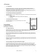
1.0 Overview 1.1 Introduction The FlexSmart Slim readers’ use the same reader electronics module. A reader can easily be configured at the site because the readers’ bezels can be interchangeably snapped on the common reader module. The following is a quick installation procedure. The FlexSmart Arch and Wave readers mount on any North American standard electrical gang box or on any flat surface, with snap on bezels. See pages 5 and 6. 1.
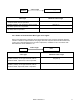
Readers Cable Length Cable Type Power Supply Maximum Cable Length 24 AWG (0.60mm), three conductors, with an overall foil shield, 9533 or equivalent. 22 AWG (0.80mm), two conductors, with an overall foil shield, Alpha 5192 or equivalent. 18 AWG (1.20mm), two conductors, with an overall foil shield, 5836 or equivalent. 200’ (61 m) 300’ (91 m) 500’ (152 m) 2.2.
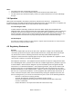
2.3 Electrical Installation 2.3.1. Grounding Connect the reader directly to an earth ground. An earth ground can be established by driving a copper clad ground rod into the earth. Make certain the DC resistance between your established earth ground and the system ground is 50 Ohms or less.
Notes: • The system must have a single earth ground point. • As shown above, do not connect shield (screen) wire at FlexSmart reader cable splice. • For open collector (non-terminated output), consult your system manufacturer for correct cable length and type. 3.0 Operation When power is first applied to the reader, it performs an internal circuit Self Test™. If it appears to be functioning properly, the reader will flash the amber LED and beep twice.
4.2 UL This Proximity Reader is intended to be powered from a limited power source output of a previously certified power supply. K02017-000 Rev.
K02017-000 Rev.