5370 Barranca Parkway Irvine, CA 92618-2215 USA DTC4500 User Guide P/N: L001444
© 2010 HID Global Corporation All rights reserved DTC4500 Card Printer/Encoder User Guide (Rev 1.0), © 2010 property of HID Global Corporation. All rights reserved. Exclusive permission is granted to authorized resellers of HID Global products to reproduce and distribute this copyrighted document to authorized HID Global customers, who have signed a no disclosure agreement regarding the restricted, proprietary use of said document.
© 2010 HID Global Corporation All rights reserved Table of Contents DTC4500 User Guide ______________________________________________________________________ 1 Section 1: Specifications ___________________________________________________________________ 5 Regulatory Compliances ___________________________________________________________________________ 5 Agency Listings__________________________________________________________________________________ 6 United States _______________________________________
© 2010 HID Global Corporation All rights reserved |contextid=100Using the K Panel Resin tab ___________________________________________________________ 66 |contextid=120Using the Printer Info tab______________________________________________________________ 69 Section 5: Selecting the Fluorescent Panel Ribbon Type________________________________________ 70 Creating a Custom Fluorescent Image (using the YMCFKO Ribbon) _____________________________________ 70 Configuring Fluorescent Data (F-Panel for YMCFK
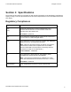
© 2010 HID Global Corporation All rights reserved Section 1: Specifications The purpose of this section is to provide you with specific information on the Regulatory Compliances, Agency Listings, Technical Specifications and Functional Specifications for the DTC4500 Card Printer User Guide. Regulatory Compliances Term Description CSA The Printer manufacturer has been authorized by UL to represent the Card Printer as CSA Certified under CSA Standard C22.2 No. 60950-1-03.
© 2010 HID Global Corporation All rights reserved Agency Listings Term Description Emissions Standards CE, FCCPart 15 Class A, CRC c1374, CISPR22 Class A, Safety Standards UL IEC 60950-1 (2001), CSA C22.2 No. 60950-1-03. EN55022, EN55024, EN61000-3-2, EN61000-3-3, United States This device complies with Part 15 of the FCC rules. Operation is subject to the following two conditions: (1) This device may not cause harmful interference.
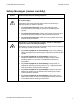
© 2010 HID Global Corporation All rights reserved Safety Messages (review carefully) Symbol Critical Instructions for Safety purposes Danger: Failure to follow these installation guidelines can result in death or serious injury. Information that raises potential safety issues is indicated by a warning symbol (as shown to the left). Caution: • To prevent personal injury, refer to the following safety messages before performing an operation preceded by this symbol.
© 2010 HID Global Corporation All rights reserved Environmental Protection (China-RoHS) Environmental Protection Use Period is based on the product being used in an office environment.
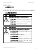
© 2010 HID Global Corporation All rights reserved Simplified Chinese 如何使用本手册 实际上,DTC4500 证卡打印机用户指南 是一本整个证卡打印机的故障排除和服务手册。本手册旨在帮助安装人员和技术人员快速有效地查找相关 过程、组件和术语。安装人员或技术人员可根据自己的喜好,高效地使用本手册的电子文档或纸面文档。 安全消息(请仔细阅读) 符号 安全事项的重要说明 危险: 如果不遵循这些安装指南进行操作,可能会导致重伤,甚至死亡。 可能引发安全问题的信息由警告符号(如左图所示)来表示。 为了确保人身安全,在执行前面带有此符号的操作之前,请先阅读下面 的安全消息。 为了确保人身安全,除非另有规定,否则在执行维修过程前,始终应断 开电源。 为了确保人身安全,只能由有资格的人员执行这些过程。 安全消息(请仔细阅读) 符号 安全事项的重要说明 小心: 此设备为静电敏感设备。如果暴露在静电电流下,可能会损坏设备。 可能引发静电安全问题的信息由警告符号(如左图所示)来表示。 为了防止设备或介质受损,在执行前面带有此符号的操作之前,请
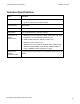
© 2010 HID Global Corporation All rights reserved Technical Specifications Term Function Print resolution • 300 x 300 dpi(11.8 dots/mm) • Up to 16.7 million colors, Monochrome Printer Memory 16MB RAM Print Area CR-80 (3.375"L x 2.125"W / 85.
© 2010 HID Global Corporation All rights reserved Technical Specifications Term Function Connectivity • Standard USB 2.
© 2010 HID Global Corporation All rights reserved Technical Specifications Term Function Card Size and Types Supported • CR-80 (3.362"L x 2.114"W / 85.4mmL x 53.7mmW) • CR-79 (3.303”L x 2.051”W / 83.7mmL x 51.9mmW • 10 mil to 40 mil card thickness • Re-writable card technologies (requires special rewritable cards) • PVC, Polyester cards with a polished PVC finish Printer Dimensions DTC4500 : • 14.4"(366 mm)L x 9.2"(234 mm)W x 9.8"(249 mm)H w/o output bin • 18.1"(460 mm)L x 9.2"(234 mm)W x 9.
© 2010 HID Global Corporation All rights reserved Functional Specifications This Card Printer utilizes two different, yet closely related printing technologies to achieve its remarkable direct-to-card print quality for dye-sublimation and resin thermal transfer. Printer Components: Print Ribbons The Card Printer utilizes both dye-sublimation and/or resin thermal transfer methods to print images directly onto blank cards.
© 2010 HID Global Corporation All rights reserved Ribbon Types/Count Table Ribbon type and count used in each Printer.
© 2010 HID Global Corporation All rights reserved Printer Components: Blank Cards Type Description Card Size The Card Printer accepts standard CR-80 and CR-79 sized cards. Card Surface Suitable cards must have a polished PVC surface free of fingerprints, dust or any other types of embedded contaminants. In addition, cards must have a completely smooth, level surface in order for the Printer to achieve consistent color coverage.
© 2010 HID Global Corporation All rights reserved Section 2: Setup and Installation Procedures This section describes the setup and installation for the DTC4500 Card Printer. Choosing a Good Location Follow these guidelines: • Place the unit in a location with adequate air circulation to prevent internal heat build up. • Use the Printer's dimensions as a guideline for the minimum clearances to the unit.
© 2010 HID Global Corporation All rights reserved Installing the Print Ribbon Cartridge (DTC4500) Fargo Card Printers require highly specialized supplies to function properly. • The Fargo DTC4500 Card Printer uses a one-piece, refill system. • To maximize Printer life, reliability, printed card quality and durability, you must use only Fargocertified supplies. • For this reason, your Fargo warranty is void, where not prohibited by law, if you use non-Fargocertified supplies.
© 2010 HID Global Corporation All rights reserved Installing the Ribbon Step 3 Procedure a. Close the Cleaning Roller Cover. b. Insert the new Cleaning roller. 4 Load the Ribbon Cartridge into the Printer. 5 Close the Front Cover.
© 2010 HID Global Corporation All rights reserved Installing Blank Cards into the Card Hopper (DTC4500) Using the Single and Dual Hopper Caution: Do not run the cards with a contaminated, dull or uneven surface through the Printer. Step 1 Procedure Pre-instruction. • Printing onto such cards will ultimately lead to poor print quality and will greatly reduce the life of the Printhead. Card Types include PVC or PVC finish. • Cards eject into the Output Hopper or Reject Hopper.
© 2010 HID Global Corporation All rights reserved Using the Single and Dual Hopper Step 2 Procedure Open the Card Hopper Cover. Single Hopper 3 Dual Hopper Press the Card Hopper Load Lever down until the Card Tray locks into place.
© 2010 HID Global Corporation All rights reserved Using the Single and Dual Hopper Step 4 Procedure Load up to 100 cards into the Hopper with the print side down. (Note: If using cards with a magnetic stripe, the magnetic stripe should be loaded with the stripe up and to the front of the Printer.
© 2010 HID Global Corporation All rights reserved Using the Single and Dual Hopper Step 5 Procedure Close the Card Hopper Cover to release the lever to the printing position.
© 2010 HID Global Corporation All rights reserved Setting the Card Size for CR79 and CR80 Follow this procedure in the Printer and in the Printer Driver to setup the card size. Step 1 Procedure Open the front door and locate the slide bar.
© 2010 HID Global Corporation All rights reserved Setting the Card Size for CR79 and CR80 Step 2 Procedure If using the CR79 card, push the slide bar to the LEFT.
© 2010 HID Global Corporation All rights reserved Setting the Card Size for CR79 and CR80 Step 3 Procedure If using the CR80 card, push the slide bar to the RIGHT.
© 2010 HID Global Corporation All rights reserved Setting the Card Size for CR79 and CR80 Step 4 Procedure From the Driver Printing Preferences, select the correct card size.
© 2010 HID Global Corporation All rights reserved Connecting the Printer power Follow this procedure. (Note: Do not connect the Printer’s USB cable until prompted during the Printer Driver installation.) Step Procedure 1 Plug the AC adapter power cable into the back of the Printer. 2 Plug the wall power cable into the AC power adapter. This display shows Printer from behind with AC power cable. 3 Plug the wall power cable into a standard 110VAC power outlet.
© 2010 HID Global Corporation All rights reserved Section 3: Print Driver Installation This section describes the Printer Driver installation requirements and standard procedures. Requirements are listed below. The DTC4500 Print Driver supports the following: • Vista, 32 bit Windows OS, • Windows XP • Server 2003 • Vista, 64 bit Windows OS • Linux OS (Ubuntu7.10, Red Hat Enterprise Desktop 5, Fecora Core 7 & 8, openSUSE 10.3 , open NOVELL SUSE 10.).
© 2010 HID Global Corporation All rights reserved Section 4: Printer Preferences Tab Functions This section provides an overview of the Printer Driver preferences tab. |contextid=30 Using the Card tab Click on the Card tab to bring up the window (shown below). Refer to the Help file for the Fargo Workbench Utility Program and User Guide.
© 2010 HID Global Corporation All rights reserved Using the Toolbox Options DTC4500 Card Printer/Encoder User Guide 30
© 2010 HID Global Corporation All rights reserved |contextid=150 Using the Configuration Tab This option is used to show the currently installed Optional Printer features, Event Monitoring, to set the Printer Driver language and Printer LCD Display language. • To switch between languages, select the desired language and reboot the driver.
© 2010 HID Global Corporation All rights reserved |contextid=151 Selecting the Calibrate Laminator tab The Calibrate Laminator tab is active when the Laminator is automatically detected or when the Laminator is manually checked (as a Printer Feature on the Configuration tab). If the Laminator is not detected and not manually checked, the tab is active; however, all functions are grayed out. • Calibrate button: Sends calibrate Laminator command to Printer.
© 2010 HID Global Corporation All rights reserved Selecting the Calibrate Laminator tab DTC4500 Card Printer/Encoder User Guide 33
© 2010 HID Global Corporation All rights reserved Using the Event Monitoring Group Box This Event Monitoring group box displays the Low Supplies (Ribbon, Laminate and Film). • The default setting is checked. If checked, the Ribbon Low message box is displayed with every print job when Printer reports low Ribbon to the Driver. • Do not show this message again: The check box allows the User to suppress message per Driver instance. Default = unchecked.
© 2010 HID Global Corporation All rights reserved |contextid=152 Selecting the Calibrate Ribbon tab The two buttons for the Calibrate Ribbon tab are described below. • Calibrate button: Sends the Calibrate Ribbon Command to Printer. Follow the instructions below to set up the Printer. • Help button: Launches help specific to this tab. Step 1 Procedure Select the Calibrate Ribbon tab. a. Ensure that the Ribbon Cartridge is removed. b. Ensure the Printer’s Cover is closed. c. Click on the Calibrate button.
© 2010 HID Global Corporation All rights reserved Selecting the Calibrate Ribbon tab DTC4500 Card Printer/Encoder User Guide 36
© 2010 HID Global Corporation All rights reserved |contextid=154 Selecting the Clean Printer tab The button for the Clean Printer tab is described below. • Clean Button: Launches cleaning routine. Follow the instruction on the page for setting up the Printer. • Help button: Launches help that is specific to this tab. • Also see Cleaning the Printer for full instructions.
© 2010 HID Global Corporation All rights reserved |contextid=155 Selecting the Advanced Settings tab Use the Advanced Settings tab for adjusting the internal Printer settings, which are customized for every Printer at the factory and saved directly within the Printer's memory. (Note: You can select the Restore Defaults to restore the internal default settings.) Selecting the Advanced Settings tab These change values for Firmware settings. See below.
© 2010 HID Global Corporation All rights reserved Selecting the Advanced Settings tab Example: DTC4500 Card Printer/Encoder User Guide 39
© 2010 HID Global Corporation All rights reserved Selecting the Advanced Settings tab Setting Image Darkness Option Use this option to set the overall darkness of the printed image by increasing or decreasing the amount of heat (used by the Printhead when printing). Caution: If the value is set too high, the Ribbon may jam or even break. Mag Top of Form Use this option to shift the starting point where the Printer begins to encode the magnetic track data on the card’s Magnetic Stripe.
© 2010 HID Global Corporation All rights reserved Selecting the Advanced Settings tab Setting Print Top of Form Option Use this option to adjust the length-wise or horizontal position of the printed image on the card (so it appears to be centered). Caution: If the negative value is set too high, the Print Ribbon may break. Print End of Form Use this option to reduce or increase the overall printable area; this is done in order to optimize edge to edge printing toward the trailing edge of the card.
© 2010 HID Global Corporation All rights reserved Selecting the Advanced Settings tab Setting Ribbon Calibrate Green Option This is a calibration driven value and should not be adjusted. (Note: This is factory set and should not be changed unless directed by a technician.) Ribbon Green LED Level This is a calibration driven value and should not be adjusted. (Note: This is factory set and should not be changed unless directed by a technician.
© 2010 HID Global Corporation All rights reserved Selecting the Advanced Settings tab Setting Option Flipper Lam Height Offset This is a calibration driven value and should not be adjusted. If the Flipper unit is replaced and has not been calibrated this value may need to be adjusted. (Note: This is factory set and should not be changed unless directed by a technician.
© 2010 HID Global Corporation All rights reserved Selecting the Advanced Settings tab Setting Option Head Resistance This is factory set. If the main board or the Printhead is replaced then adjust this number. Locate the Printhead Setting Number on the bottom of the Printhead. The number reads R=XXXX. Head Home Offset This is a calibration driven value and should not be adjusted. If the Printhead assembly is replaced then this value may need to be adjusted.
© 2010 HID Global Corporation All rights reserved Selecting the Advanced Settings tab Setting Option Write Heat Offset Adjust the Write temperature for the rewriteable cards as needed. • Increase the Current Setting to cause more heat to be used in the printing process of a rewritable card. OR • Decrease the Current Setting to cause less heat to be used in the printing process of a rewritable card.
© 2010 HID Global Corporation All rights reserved |contextid=40Using the Device Options tab Click on the Device Option tab to bring up the window (shown below).
© 2010 HID Global Corporation All rights reserved Using the Device Options tab DTC4500 Card Printer/Encoder User Guide 47
© 2010 HID Global Corporation All rights reserved Using the Device Options tab DTC4500 Card Printer/Encoder User Guide 48
© 2010 HID Global Corporation All rights reserved |contextid=50Using the Image Color tab Click on the Image Color option tab to bring up the window (shown below).
© 2010 HID Global Corporation All rights reserved Using the Image Color tab DTC4500 Card Printer/Encoder User Guide 50
© 2010 HID Global Corporation All rights reserved Using the Image Color tab DTC4500 Card Printer/Encoder User Guide 51
© 2010 HID Global Corporation All rights reserved |contextid=51Using the Image Calibrate tab Use the Image Calibrate tab to control the position of the printable area in relation to the card.
© 2010 HID Global Corporation All rights reserved |contextid=70Using the Magnetic Encoding Tab Select the Magnetic Encoding tab to display options for controlling the Magnetic Stripe encoding process.You should use these options only if the Printer has an optional Magnetic Stripe Encoding Module installed.
© 2010 HID Global Corporation All rights reserved Using the Magnetic Encoding Tab – ISO Standards You can change the encoding mode and coercivity setting or modify the ISO standards for Tracks 1, 2 and 3. This can be done by correctly modifying these Magnetic Encoding options. Window TAB Procedure Procedure (continued) If you select ISO Encoding, you send down a formatted set of characters. This selection activates the track tabs.
© 2010 HID Global Corporation All rights reserved Using the Magnetic Encoding Tab – ISO Standards Window TAB Procedure If you select JIS II Encoding, specific standards are used. Procedure (continued) This selection disables all the Magnetic Track Options tabs. It also disables the Coercivity dropdown function and Shift Data Left checkbox option. The default Coercivity is 600 Oe. Select the Coercivity option (Oersted) to use the Magnetic Stripe type that matches the card type.
© 2010 HID Global Corporation All rights reserved Using the Magnetic Encoding Tab – Custom Encoding or Raw Binary Encoding Mode You can change the Magnetic Track options for Tracks 1, 2 and 3 when using the Custom Encoding or Raw Binary Encoding Mode. These options are not availabe for ISO or JIS II encoding. Window TAB Procedure Procedure (continued) Select 4 Bits to change the bits per character to 4 BPC. (Note: This is the default for Track 3).
© 2010 HID Global Corporation All rights reserved Using the Magnetic Encoding Tab – Custom Encoding or Raw Binary Encoding Mode Window TAB Procedure Procedure (continued) Select No LRC to change the LRC Generation to none. Select Odd Parity to change the LRC Generation to Odd Parity. Select Even Parity to change the LRC Generation to Even Parity. (Note: This is the default for all tracks.) Select No Parity to change the Character Parity to none.
© 2010 HID Global Corporation All rights reserved Reviewing the Sample String • Track 1: ~1%JULIEANDERSON^1234567890? • Track 2: ~2;1234567890987654321? • Track 3: ~3;1234567890987654321? Track Start Sentinel End Sentinel Field Separator Track 1 % ? ^ Track 2 ; ? = Track 3 ; ? = DTC4500 Card Printer/Encoder User Guide Valid Characters ASCII 32-95 (See the table below.) ASCII 48-63 (See the table below.) ASCII 48-63 (See the table below.
© 2010 HID Global Corporation All rights reserved Sending the Track Information Magnetic track data is sent in the form of text strings from the application software to the Printer Driver. • In order for the Printer Driver to differentiate between Magnetic Track data and the rest of the printable objects, specific characters must be added to the magnetic data to be encoded. • These specify the data that is to be encoded, the tracks to encode and mark the start and stop of the data string.
© 2010 HID Global Corporation All rights reserved Reviewing the ASCII Code and Character Table ASCII Code Character ASCII Code Character ASCII Code Character 32 space 56 8 80 P 33 ! 57 9 81 Q 58 : 82 R 34 35 # 59 ; 83 S 36 $ 60 < 84 T 37 % 61 = 85 U 38 and 62 > 86 V 39 ' 63 ? 87 W 40 ( 64 @ 88 X 41 ) 65 A 89 Y 42 * 66 B 90 Z 43 + 67 C 91 [ 44 ' 68 D 92 \ 45 - 69 E 93 ] DTC4500 Card Printer/Encoder User Guide 60
© 2010 HID Global Corporation All rights reserved Reviewing the ASCII Code and Character Table ASCII Code Character ASCII Code Character ASCII Code Character 46 .
© 2010 HID Global Corporation All rights reserved |contextid=80Using the Lamination tab Use the Image Calibrate tab to control the position of the printable area in relation to the card. |contextid=90 Using the Overlay / Print Area tab This option is helpful if, for example, you would like to omit the printing or block out the overlay for a signature or printing around a card's smart chip or Magnetic Stripe. Refer to Using the Defined Area Option for a specific procedure that relates to this tab.
© 2010 HID Global Corporation DTC4500 Card Printer/Encoder User Guide All rights reserved 63
© 2010 HID Global Corporation All rights reserved Using the Overlay / Print Area tab DTC4500 Card Printer/Encoder User Guide 64
© 2010 HID Global Corporation All rights reserved Using the Overlay / Print Area tab DTC4500 Card Printer/Encoder User Guide 65
© 2010 HID Global Corporation All rights reserved |contextid=100Using the K Panel Resin tab Use this tab to control where the resin black (K) Panel of a full-color Ribbon is printed. Refer to Using the Defined Area Option for a specific procedure that relates to this tab.
© 2010 HID Global Corporation All rights reserved Using the K Panel Resin tab DTC4500 Card Printer/Encoder User Guide 67
© 2010 HID Global Corporation All rights reserved Using the K Panel Resin tab DTC4500 Card Printer/Encoder User Guide 68
© 2010 HID Global Corporation All rights reserved |contextid=120Using the Printer Info tab Use the options on this tab to view information about the Ribbon, Laminate, Card Count, Printer Serial #, Firmware version, and Reorder Media #’s installed in the Printer.
© 2010 HID Global Corporation All rights reserved Section 5: Selecting the Fluorescent Panel Ribbon Type The YMCFKO/YMCFKOK Ribbon is an economical way to add a fully customizable, incremental level of security to your photo identification cards. • Process: This process allows you to configure the data that is printed with the fluorescent panel of an YMCFKO/YMCFKOK Ribbon.
© 2010 HID Global Corporation All rights reserved Creating a Custom Fluorescent Image (using the YMCFKO Ribbon) DTC4500 Card Printer/Encoder User Guide 71
© 2010 HID Global Corporation All rights reserved Configuring Fluorescent Data (F-Panel for YMCFKO Ribbon) using the Application This process creates a fluorescent image on your card using a simple text string command in your badge application. Step Procedure 1 Creating Fluorescent Text: Create a new text box in your badge application. 2 Type the TEXT that you want to appear as fluorescent and put a ~T before the start of the text with no space after the ~T.
© 2010 HID Global Corporation All rights reserved Configuring Fluorescent Data (F-Panel for YMCFKO Ribbon) using the Application Step Procedure 3 Creating a Fluorescent Image: In a separate drawing program, create the image that you wish to fluoresce. (See Display C below.) 4 Create the IMAGE in the actual size that you want it to appear on the card, and save it as a Grayscale or 1 - bit bmp file on the root c:\ directory. • Do not put spaces in the file name.
© 2010 HID Global Corporation All rights reserved Configuring Fluorescent Data (F-Panel for YMCFKO Ribbon) using the Application Step Procedure 6 Set up the Printer Driver preferences. Refer to Step 8-10 below. 7 Printer will print the fluorescent BMP IMAGE at the ~I position on the card. Printer will print the fluorescent TEXT at the ~T position on the card. (See Display B below) BMP Image located at c:\globe.bmp 8 Set the Ribbon for YMCFKO in the Printing Preferences.
© 2010 HID Global Corporation All rights reserved Configuring Fluorescent Data (F-Panel for YMCFKO Ribbon) using the Application Step 10 Procedure Check Invert F-Panel Image to create a negative of the fluorescent image. See below. • This refers to the ability to cause light or white areas of the image to fluoresce and dark colors to remain dark on the printed card when exposed to a UV light. • This was requested because the fluorescent dye color is bright when black light is applied to it.
© 2010 HID Global Corporation All rights reserved Section 6: System Overview- Troubleshooting Reviewing the DTC4500 Sequence of Operations Knowing the sequence of the Printer operation will help troubleshoot the printer. Step Process 1 The File information is received from PC. 2 Printer checks the installed Ribbon type stored in memory against the Ribbon type command that was sent from the Printer. If Ribbon type does not match, the Pause button on the right will begin flashing.
© 2010 HID Global Corporation All rights reserved Reviewing the DTC4500 Sequence of Operations Step Process 13 The Print Stepper Motor queues card to the middle of the platen Roller. All Stop. 14 The Print Headlift Motor engages to the print position. 15 The Print Cover Sensor checks for closed state. 16 The Print Stepper Motor engages. 17 The Ribbon Drive Motor engages. 18 The Image data is burned by the Printhead until the image data is depleted. All Stop.
© 2010 HID Global Corporation All rights reserved Section 7: Troubleshooting Printer Error Button and Display Message Table Both the DTC4500 use the Button messages rather than the Display Message system. Step 1 Procedure All Printers have two (2) buttons, one for ON/Off (LEFT) and one for Pause (II) (RIGHT). 2 The ON/Off button is blue when the Printer is ON. When the Printer enters the Sleep Mode, the LED is dimmed but still ON.
© 2010 HID Global Corporation All rights reserved Printer Error Button and Display Message Table Both the DTC4500 use the Button messages rather than the Display Message system. Step Procedure 5 Press the ON/Off button when Printer is in an error state to cause the action to be cancelled. (Note: If no other error occurs, then the Pause button will illuminate its blue LED.) 6 Press the Pause button when Printer is in an error state to cause the Printer to retry.
© 2010 HID Global Corporation All rights reserved Using the Error Message Table This section provides the troubleshooting table for the error message. The DTC4500 has a display that will show the Printer error messages. • When an error occurs in the Printer, the PC will show the error message on screen with solutions. • The display will blink in the location needing attention.
© 2010 HID Global Corporation All rights reserved Using the Error Message Table Error Message # 81 Unable to Feed Cause Solution The Printer is unable to feed a card from the Card Hopper. Check the following, then press the Pause button to continue. • Verify the card thickness setting is set to the thickness of your cards. • Verify the Cleaning roller is properly installed on the Ribbon Cartridge. • Check for card slippage. If necessary, run the Printer cleaning routine.
© 2010 HID Global Corporation All rights reserved Troubleshooting with the Error Message Table Error Message Cause Solution #2 This is a problem with the Printhead Lift. Reset the Printer and try again. The Printhead Temperature Sensor is not functioning or is not connected properly. OR The Printhead is not cooling properly. Reset the Printer and try again. Unspecified system error detected by the Printer Firmware. Reset the Printer and try again. A Ribbon is not installed in the Printer.
© 2010 HID Global Corporation All rights reserved Troubleshooting with the Error Message Table Error Message Cause Solution # 30 Magnetic encoding verification failure. • Try encoding with a different card. Mag Verify Error • Verify cards have the Magnetic Stripe. |contextid=251 |contextid=252 # 31 No Mag Module |contextid=250 # 38 # 39 • Replace the Magnetic Encoding Module. You are trying to send encoding data, but the Printer is not configured with this Encoder type.
© 2010 HID Global Corporation All rights reserved Troubleshooting with the Error Message Table Error Message Cause Solution # 44 A card has become jammed in the Printer’s Flipper Table. Clear any cards in the Flipper Table using the buttons to move the card out. Resume printing. The Flipper failed to position properly while aligning a card or flipping a card. • Reset the Printer and retry. If problem persists call for technical assistance.
© 2010 HID Global Corporation All rights reserved Troubleshooting with the Error Message Table Error Message # 53 Lam Card Jam # 63 Cause Solution A jam occurred somewhere between the Printer and the laminator Open covers and clear the obstruction/jam There is no material loaded in the laminator Load material into the Laminator Unspecified system error detected by the Printer Firmware. Reset the Printer and try again. A card is jammed in the Print Station or card flipping area of the Printer.
© 2010 HID Global Corporation All rights reserved Troubleshooting with the Error Message Table Error Message Cause Solution # 81 The Printer is unable to feed a card from the Card Hopper. Check the following, then press the Pause button to continue. Unable to Feed |contextid=214 |contextid=210 • Verify the card thickness setting is set to the thickness of your cards. • Verify the Cleaning roller is properly installed on the Ribbon Cartridge. • Check for card slippage.
© 2010 HID Global Corporation All rights reserved Troubleshooting with the Error Message Table Error Message Cause Solution # 91 The Print Ribbon has run out. • Install a new Ribbon. The Print Ribbon installed in the Printer does not match the Ribbon type selected in the Printer Driver. • Change either the installed Print Ribbon or the Ribbon type selected in the Printer Driver.
© 2010 HID Global Corporation All rights reserved Troubleshooting with the Error Message Table Error Message Cause Solution # 99 The Print Ribbon has either broken or jammed. • If jammed, clear the jam. Ribbon Error |contextid=234 • If broken, repair by taping the Ribbon back on to the take- up core. • Press the Pause button to continue or the ON/OFF button to cancel. # 100 Ribbon RFID Error There is no Ribbon or the Ribbon tag information is corrupted or incorrect.
© 2010 HID Global Corporation All rights reserved Troubleshooting with the Error Message Table Error Message Cause Solution # 107 An error was detected during printing. Reset the Printer and try again. The Printer cannot locate the next Ribbon panel in order to release the Ribbon from the card. Ensure that the Ribbon is not stuck to the card. Printing Error # 109 Ribbon Release Error • If this problem persists, call for technical assistance. • Replace the Ribbon.
© 2010 HID Global Corporation All rights reserved Troubleshooting with the Error Message Table Error Message Cause Solution # 113 The Printer cannot locate the next Ribbon panel in order to release the Ribbon from the card. Ensure that the Ribbon is not stuck to the card. Ribbon Release Error • Replace the Ribbon. • Recalibrate the Ribbon sensor. • If the Ribbon is broken, repair by taping the Ribbon back onto the take- up core and manually advance to the next panel.
© 2010 HID Global Corporation All rights reserved Troubleshooting with the Error Message Table Error Message Cause Solution # 136 Printing is disabled by SecureGuard until a password is received. Reset the Printer and retry. Ribbon needs to be removed. Reset the Printer and retry. EEPROM restored with factory default values. • If changes were made in the Advanced Setting Tab in the Printer Driver, click the Default button to reset these numbers.
© 2010 HID Global Corporation All rights reserved Printer Specific Tools (DTC4500) Here is a description of these tools. • Press the • Press the button to scroll through the details of the Printer and perform the action. button to select the option. • Once is selected, use the left down arrow and Languages and Exit. • Use the corner arrow • The curved arrow to scroll through the Info, Test Prints, to run that option. will return to the first screen.
© 2010 HID Global Corporation All rights reserved Additional Printer Specific Tools (DTC4500) Label Description INFO • Printer Type • Firmware Version • I.P Address • Flipper • Lamination • Magnetics • E-Card • Password • Card count TEST PRINTS Color Photo: Select this to print a color card to test communication and integrity. Alignment: Select this to print a card used to align the print image on the card. Settings: Select this to print a card with the Advanced settings.
© 2010 HID Global Corporation All rights reserved Section 8: Cleaning The Card Printer is built to require a minimum amount of maintenance. Nevertheless, there are a few procedures you can perform on a regular basis or as needed to ensure the best possible performance Safety Messages (review carefully) Symbol Critical Instructions for Safety purposes Danger: Failure to follow these installation guidelines can result in death or serious injury.
© 2010 HID Global Corporation All rights reserved DTC4500 Card Printer/Encoder Cleaning Kit Caution: As with any electronic device, internal components of the Printer, such as the Printhead, may be damaged if exposed to static electrical discharges. To avoid potential damage, always wear an appropriate personal grounding device, such as a wrist strap (with integral resistor) connected to an ESD ground.
© 2010 HID Global Corporation All rights reserved Printhead Cleaning Step Procedure 1 Caution: Turn Off the Printer and unplug the power cord from the Printer. 2 Remove the Ribbon Cartridge. 3 Open the Printhead Cleaning Swabs. Break it to moisten the tip. 4 Swab the tip back and forth across the top of the Printhead. Allow to dry thoroughly before sending a print job.
© 2010 HID Global Corporation All rights reserved Cleaning the Platen and the Card Feed Rollers Perform this procedure approximately every 1000 prints to maintain a consistent print quality. (Note: The Card Feed Rollers move the card throughout the print process. Rollers should be kept clean to prevent card jams and card contamination. This cleaning process will ultimately lead to better print quality and extended Printhead life.) Step 1 Procedure Picture a.
© 2010 HID Global Corporation All rights reserved Cleaning the Platen and the Card Feed Rollers Step Procedure 4 From your computer, open the Printer Driver and select Printing Preferences. 5 Open the Toolbox button. 6 Click on the Clean Printer button. 7 Click on the Clean button. Picture • The Printer will pull in the Cleaning Card. The Printer will then perform an automated cleaning procedure.
© 2010 HID Global Corporation All rights reserved Cleaning the Printer’s Interior Periodically, use a Cleaning Pad from the Printer’s Cleaning Kit to remove dust and other contaminants from inside the Printer. (Note: Dust and other particles may accumulate inside the Printer with continued usage. This can cause spots or specks to appear on the printed cards.) Cleaning the Printer’s Exterior Clean it only with a Cleaning Pad from the Printer’s Cleaning Kit.
© 2010 HID Global Corporation All rights reserved Section 9: Firmware Upgrades Upgrade the Printer Firmware Step 1 Procedure Requirements • Internet Access • Printer is powered up and connected to PC 2 Open the Fargo Workbench Printer Utility and use the Diagnostics button from the Card Option Printing Preference page. (Note: The Workbench is also available from the Fargo Folder in the Windows Program folder.) 3 From the Application Icon, select Upgrade Firmware.
© 2010 HID Global Corporation All rights reserved Upgrade the Printer Firmware Step 4 Procedure Find the Firmware via Check for Firmware Updates at www.hidglobal.com • Save the file to a folder. • Use the Browse button to find the .frm file. • Select the file. Click Open.
© 2010 HID Global Corporation All rights reserved Upgrade the Printer Firmware Step Procedure 5 Click on Upgrade to start the upgrade process. 6 This message will appear while Firmware is updating. 7 The Printer will reboot after this process is completed.
© 2010 HID Global Corporation All rights reserved Section 10: HID Global Technical Support The purpose of this section to provide you with an efficient, step-by-step procedure to be used when contacting HID GLOBAL Technical Support as needed for this Card Printer. Step 1 Procedure Contact the HIDGlobal Technical Support Group by phone at (866)607-7339 Ext #6 or by fax at (952) 946-8492 for additional technical assistance. OR Contact HID Technical Support via the Web: www.hidglobal.
© 2010 HID Global Corporation All rights reserved Reading the Serial Numbers on a Fargo Printer You can determine when your card Printer was manufactured by reading directly from the serial number (affixed to your card Printer). Example Explanation Reviewing Example No. 1: Serial Number A9050028 ( 2009) • A9050028: The first two digits in the serial number indicate the year the Printer was built (e.g., the digits A9 indicate the year 2009).
© 2010 HID Global Corporation All rights reserved Appendix A Using the Defined Area Option This procedure can be used with the K Panel or the Overlay /Print Area procedure to define specific areas. The K-Panel procedure is described below: The same process is used for the Overlay/Print Area option.
© 2010 HID Global Corporation All rights reserved Configuring Fluorescent Data (F-Panel for YMCFKO Ribbon) using the Workbench Step Procedure 1 From the Driver Printing Preferences, click on Diagnostics to bring up the Fargo Workbench Printer Utility. 2 a. Click the Print Security applet group and select the Security Imaging applet. b. Check the Enable Secure Imaging checkbox. (Note: The option for both front and back are set up the same way.
© 2010 HID Global Corporation All rights reserved Configuring Fluorescent Data (F-Panel for YMCFKO Ribbon) using the Workbench Step Procedure 3 a. Click on the Secure ID box on the left. b. Click and drag a box onto the Template. c. Move and size as needed.
© 2010 HID Global Corporation All rights reserved Configuring Fluorescent Data (F-Panel for YMCFKO Ribbon) using the Workbench Step Procedure 4 On the Template, right click on the Secure ID box for the options.
© 2010 HID Global Corporation All rights reserved Configuring Fluorescent Data (F-Panel for YMCFKO Ribbon) using the Workbench Step Procedure 5 a. Click on the Logo box on the left. b. Click and drag a box onto the Template. c. Move and size (as needed) by grabbing the corner of the box.
© 2010 HID Global Corporation All rights reserved Configuring Fluorescent Data (F-Panel for YMCFKO Ribbon) using the Workbench Step Procedure 6 On the Template right click on the Logo box for the options shown below. 7 Select the Logo File. Find the source of the Logo to place on the card. (Note: Fit to Frame will size the image to fit the box. Once this is set up, this logo will print from the software program. This is set up in the background.
© 2010 HID Global Corporation All rights reserved Configuring Fluorescent Data (F-Panel for YMCFKO Ribbon) using the Workbench Step 8 Procedure a. Click on the Text box on the left. b. Click and drag a box onto the Template. c. Move and size as needed.
© 2010 HID Global Corporation All rights reserved Configuring Fluorescent Data (F-Panel for YMCFKO Ribbon) using the Workbench Step 9 Procedure On the Template, right click on the Text box for the options.
© 2010 HID Global Corporation All rights reserved Configuring Fluorescent Data (F-Panel for YMCFKO Ribbon) using the Workbench Step Procedure 10 Follow the same instruction as above for the back side of the card. 11 a. Save this template using the Save button b. Close the Workbench. (Note: Any Software program file printed with the YMCFKO Ribbon installed into the Printer will print this design with the FPanel of the Ribbon. It will print the same file each time unless you recreate a new template.
© 2010 HID Global Corporation All rights reserved Configuring Fluorescent Data (F-Panel for YMCFKO Ribbon) using the Workbench Step Procedure 12 Set the Ribbon for YMCFKO in the Printing Preferences. (Note: The Detect Supplies at Print Time button may also be used. The F-Panel Ribbon must be installed for this process to work.) 13 Check Dual Pass if you would like to print the F-Panel on a separate panel of HDP film from the YMC image.