
User's Guide


8.2 Setup and Installation of Encoder Module
8.2.1 Unpacking and Inspection
In addition to the 3 shipment boxes described in the “Connecting Modules (General Configuration)”,
the Encoder module is shipped separately in a 4
th
box
While unpacking the Encoder module, inspect the carton to ensure that damage did not occur during
shipping.
Make sure that all supplied accessories are included with the unit:
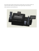
• Encoder Module
I2C Ribbon cable
Ethernet cable (length?)
Module alignment guide
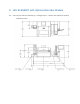
8.2.2 Connecting Modules
To connect modules including the Encoder Module, follow steps 1 and 2 A-C in the “Connecting
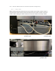
Modules (General Configuration)” section above. This includes removing the back electrical channel
covers, placing module alignment guides on both sides of the printer module, and installing the output
module.
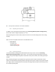
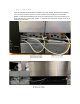
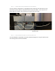
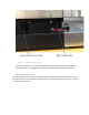
Next, instead of placing the input module to the right of the printer module as described in step D
above, place the Smartware encoding module to the right of the printer module, lining up the card path
slots. Again, holes in the baseplate of the Smartware encoding module should line up with the posts on
the module alignment guide.