
User's Guide
• Prime Input Module
▪ US/EU power cable
▪ I2C Ribbon cable
▪ Ethernet cable (12” for prime to input module)
▪ Module alignment guide
▪ Card input hopper
▪ Cleaning Roller
▪ Key for lock in input hopper
• Printer Module
▪ Overspray Liner
▪ Key for cover lock
▪ (ethernet cable length – 36” for prime to printer?)
• Output Module
▪ I2C Ribbon cable
▪ Card output hopper
▪ Module alignment guide
▪ Key for lock in output hopper
▪ Reject bin
Make sure you have these accessories that are supplied separately:
▪ Ink Cartridges (YMCKOO or WWKKOO depending on the printer option)
▪ CR-80 Cards
3.4 Connecting Modules (General Configuration)
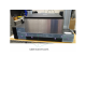
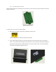
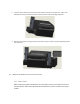
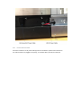
3.4.1 Removal of Electrical Channel Covers
On the back of the each module, there is a channel which is intended to hold cables that connect various
modules together, and each channel has a cover. For each module (input, printer, and output), remove
its cable channel cover by unscrewing the fasteners circled in purple in the image below.