HID ELEMENT User Guide Draft
Table of Contents 1 2 3 HID ELEMENT Specifications ................................................................................................................. 6 1.1 Regulatory Compliance ................................................................................................................. 6 1.2 Safety messages – United States .................................................................................................. 7 1.3 Technical Specifications .............................
.9.3 3.10 Loading the Input Card Hopper into the Input Module ...................................................... 29 Output Hopper ............................................................................................................................ 30 3.10.1 Loading the Output Card Hopper into the Output Module ................................................ 30 3.11 Installation of the Overspray Liner .........................................................................................
5 4.7 Replacing Ink Cartridges.............................................................................................................. 50 4.8 Replacing Full Waste Tank .......................................................................................................... 50 4.9 Input Hopper Empty (needs completion) ................................................................................... 50 4.10 Output Hopper Full (needs completion) ................................................
8.2.4 9 Cable Channel Covers.......................................................................................................... 70 Appendix ............................................................................................................................................. 71 9.1 Driver Test Certificate Installation .............................................................................................. 71 9.2 Firmware Upgrade Process (Update image after utilities cleanup) ........
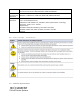
1 HID ELEMENT Specifications This section provides specific information on the Regulatory Compliances, Agency Listings, Technical Specifications, and Functional Specifications for the HID ELEMENT card printer. 1.1 Regulatory Compliance Agency UL CSA FCC Regulatory Compliance The card printer is listed under UL 60950-1 (2nd edition) Information Technology Equipment.
Emissions and Immunity Standards Safety Standards complies with the following of the European Community and has placed the CE mark on the card printer: RED 2014/53/EU, ROHS 2015/863/EU FCC Part 15 Class A, RSS-GEN, RSS 210, CNS 13438, EN55032 Class A, EN55024, EN6100-3-2, EN6100-3-3, EN300-330, EN301-489, GB9254, GB17625 UL 60950-1, 2nd Edition, 2019-05-09 (Information Technology Equipment - Safety Part 1: General Requirements) CAN/CSA C22.2 No.
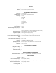
FEATURES Dual-Sided Printing Warranty Standard Printer module and printheads: 12 months UV INK PRINTER CHARACTERISTICS Printing Type Card Material Types UV Ink Types UV Cured Inkjet PVC, Composite, and Polycarbonate (PC) Yellow (Y) Magenta (M) Cyan (C) Black (K) Fluorescent (F) Clear Overlay (O) White (W) Printing Resolution Printer Ink Channels Ink Channel Configurations (Factory Set) Up to 1200 DPI Up to 6 YMCKFO YMCKOO Other Ink Configurations are available via CPO (Custom Product Order) Communicat
OPTIONS ISO Magnetic Encoding Yes Contact Smart Card Encoding Yes Contactless Smart Card Encoding Yes Camera Verification System Yes Third Party Encoder Module Available via CPO (Custom Product Order)
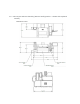
1.4 Unit Layout and Functionality (General Configuration – shown with optional camera) Dimensions in mm.
2 Important information: Please follow these recommendations. 2.1 Use caution when handling wet ink. The printer has been designed so that a user will not come into contact with wet ink. Wet ink can cause skin sensitivies and/or other hazards (please see labelling on ink cartridges for more information). If a situation occurs in which wet ink is present, users must take precautions. Gloves should be worn to prevent contact with skin, and safety glasses should be used for eye protection.
3 Setup and Installation 3.1 Selecting a good location The following guidelines help to ensure optimal printing performance: ▪ ▪ ▪ ▪ ▪ ▪ Place the unit in a location with adequate air circulation and ventilation to prevent ink fume and internal heat buildup. Use the dimensions of the printer as a guideline for the minimum clearances to the unit. Provide a table or bench for the unit which is flat and stable to prevent vibration.
• Prime Input Module ▪ US/EU power cable ▪ I2C Ribbon cable ▪ Ethernet cable (12” for prime to input module) ▪ Module alignment guide ▪ Card input hopper ▪ Cleaning Roller ▪ Key for lock in input hopper • Printer Module ▪ Overspray Liner ▪ Key for cover lock ▪ (ethernet cable length – 36” for prime to printer?) • Output Module ▪ I2C Ribbon cable ▪ Card output hopper ▪ Module alignment guide ▪ Key for lock in output hopper ▪ Reject bin Make sure you have these accessories that are supplied separately:
3.4.2 Module Alignment Guides Module alignment guides are used between the input module, printer module, and output module to locate them relative to each other. Module Alignment Guide To connect the input, printer, and output modules: A. Place the printer module on the bench or table where it will be used Caution: Lifting the print module must be done by 2 people. B. Place module alignment guides on the left and right side of the print module as shown in the images below.
C. Place the output module to the left of the printer module, lining up the card path slots. Holes in the baseplate of the output module should line up with the posts on the module alignment guide. D. Place the input module to the right of the printer module, lining it up with the module alignment guide as done previously. 3.5 Module to Module Electrical Connections 3.5.1 Ribbon Cables Ribbon Cable (A) should be installed from the input module to the printer module as shown in the photo below.
3.5.2 Ethernet Cables Install Ethernet Cable (C) from from one of the 4 ethernet ports aligned in a row in the input module to the ethernet ports on the right side of the input module . Install Ethernet Cable (D) from one of the 4 ethernet ports aligned in a row to one of the ethernet ports in the printer module. In both the input and printer module, any of the 4 ethernet ports will work. 3.5.
3.5.4 Output stacker DC power to printer DC power out The Output Module is shipped with a DC Power Cable (F) hanging loose. Plug this cable end into the matching socket of the Printer Module.
3.5.5 Unused AC Power Cable The Printer module has an AC power cable (G) which is intended for possible future extensions. This cable should not be plugged into anything. It should be held in place by the cable clips.
3.5.6 Cable Channel Covers After all cables have been installed, the cables should be carefully placed in the cable channel, and the cable channel covers should be replaced, using the opposite process of how they were removed in the description above. Be sure to install the screws which attach the covers of each module to each other.
3.6 Display Positioning The display position is adjustable, and when shipped, it is oriented to facilitate packing of the unit. Adjustments can be made to the height and viewing angle of the unit by loosening display adjustment knob 1, as shown in the image below, moving the display to the desired position, and then tightening adjustment knob 1.
Adjustments to the tilt of the display can be made by loos loosening display adjustment knob 2, as shown in the image below, moving the display to the desired position, and then tightening adjustment knob 2. 3.7 Reject Bin 3.7.1 To install non-secure reject bin A. Align both protruding hooks on backside of reject bin with the output hopper’s left side reject output hole.
B. Assure the reject hopper hooks onto the reject hopper hole with both hooks and is fully seated downward.
3.7.2 To install secure (locking) reject bin A. Insert key, unlock reject bin and lift cover 90 degrees (fully upright). B. C. Align both protruding hooks on backside of reject bin with the output hopper’s left side reject output hole.
D. Assure the reject hopper hooks onto the reject hopper hole with both hooks and is fully seated downward. E. Lower cover, lock reject bin and remove key. (Note that the locking hopper cover must be in the open/vertical position in order to install or remove the reject hopper.
3.8 Moving the Machine To move the machine from one location to another; 1. 2. 3. 4. Remove the Cable Channel Covers as described above. Remove cables described in the “Module to Module Electrical Connections” section above. Lift modules off of their Module Alignment Guides. Move modules individually. For the printer module, remember Caution: Lifting the print module must be done by 2 people. 5. Reassemble the machine as described in the “Setup and Installation” section above.
3.9 Input Hopper 3.9.1 Installing Blank Cards into the Input Card Hopper The input card hopper has a door on its front that can be opened by pulling on the black plastic handle as shown below. Cards can be loaded into the input card hopper by placing them in the bottom of hopper. Load the cards with the print side down, and if applicable, with the mag strip facing up to the left. Then close the door until the black plasctic latch snaps into place.
Note: Cards eject into the output hopper or to the reject bin. Depending on hopper option, hoppers will hold either 200 or 400 cards. 3.9.2 General card information Important: For the best results and ISO card specification compliance, composite PVC is recommended over straight PVC. The printer prints onto any card with a clean and level PVC or polycarbonate surface. Suitable cards must be free of fingerprints, dust, or any other types of embedded or surface contaminants.
To remove the input card hopper from the input module, be sure the mechanical lock is unlocked, and lift the card hopper out of the input module 3.10 Output Hopper 3.10.1 Loading the Output Card Hopper into the Output Module The output card hopper can be loaded into the output module by placing the hopper in the opening in the output module as shown below, and pressing downward until the output card hopper clicks into place.
3.
An overspray liner is used to allow for printing cards completely up to the edge of a card. Any ink which is sprayed beyond the card edge is collected and cured on the overspray liner. The liner itself is made of a flexible Teflon coated material, and it includes tabs on its left and right sides. The liner is installed on the top of the card transport as shown in the above image.
3.12.3 Ink Storage and expiration Ink should be stored at a temperature range between 15 degrees C and 30 degrees C (59F - 86F), with humidity between 40% and 80%. Ink is warrantied for 1 year from the date of manufacture. It should not be used in the printer after expiration, as it may cause damage in the system ink lines and printheads. If a printer is put into long term storage, ink should be cleared out of the system by a technician to prevent issues such as this. 3.12.
3.13 Printer Power Use the provided AC power cord to connect the socket at the back of the prime module with a standard wall outlet with the following specifications Supply voltage / Current: 100 to 240V AC, 3.5A minimum Supply frequency: 50 Hz or 60 Hz Turn the power switch at the back of the input prime module to the “On” position to provide power for the system. The power socket and power switch are shown circled in red in the image below.
When power is switched on, the printer system will automatically begin initialization and homing processes. When those processes are complete, a “Ready” screen will appear on the display.
3.14 First Fill When a system is used for the first time, the printer will go through a sequence to load ink into the machine. During this process, if an ink level fault or other error occurs, reboot the printer by turning the power switch off for 5 seconds and then on again, and the system should resume with the initial ink fill. The initial fill is complete when the “Ready” screen appears on the system display. 3.
Driver Installation 3.16 Installer for the Printer Driver The HID ELEMENT printer driver will be provided, or can be found at www.hidglobal.com/drivers. 3.17 Prerequisites The HID ELEMENT printer driver can be used on the following Windows operating systems: • Microsoft Windows 7 64-bit • Microsoft Windows 8/8.
4 System Use 4.1 Preparing for Printing at Startup or After the System Has Been Idle When the system has been unused or idle, a series of steps are necessary to achieve good print quality. 1. Open main access door. 2. Verify that the waste ink bottle is installed and that it is not full. If it is full, replace it with an empty bottle. (Firmware monitoring in being implemented for this.) 3. [White ink only] Remove all white ink cartridges from printer.
7. Print nozzle check card from user panel to assure all printhead nozzles are jetting. (This step will likely be eliminated as firmware is optimized.) If any nozzles are missing in a color, repeat deep cleans (step 6 above) until the nozzle check card shows nozzles are operational.
4.2 Display Functionality (section incomplete) 4.2.1 Home Screen The home screen can be accessed by tapping on the left edge of the display. This screen is the default display mode and shows the current printer status including print job information. The current state of the inkjet module automatic lock is displayed in the top right corner. 4.2.2 Information The information menus can be accessed by tapping on the left edge of the display.
4.2.3 Settings The settings menu can be accessed by tapping on the left edge of the display. A dialog box will appear prompting for the administrator username and password. Once authenticated, the settings menu allows for various adjustments. Menus are listed for specific modules along the left side of the screen. Tap on the desired module name to view and/or edit those settings.
(NEED TO DESCRIBE EACH SETTING HERE) Input Hopper • Smart Card Encoding • Inkjet • Output Stacker • Display • Network • Vision System •
4.2.4 Utilities The utility menus can be accessed by tapping on the left edge of the display. These menus contain various commands, test cards, and maintenance procedures. To execute a utility command, tap the corresponding explains each utility option available: and then choose “Execute”. The following list Inkjet Controls • • • • • • Calibrate Printhead Carriage Y Position: Recalibrates the y-axis leadscrews by re-homing against the hard stop.
• • • • • • • • White HID Element Card: Mag Test Card: Contact Card: Contactless Card: Clear Black Nozzles: Clear White Nozzles: Financial Card: Blank Card Test: Maintenance • • • • • • • • • Disable Printing: Disables printing while still allowing cards to feed through the system. (Password protected) Enable Printing: Re-enables printing if has been disabled. (Password protected) Clean Printer Using Sticky Card: Displays instructions for how to use a sticky card to clean the cardpath rollers.
4.2.6 Shift Change The shift change screen can be accessed by tapping on the left edge of the display.
4.2.7 Display Lock The display lock can be activated by tapping on the left edge of the display. A dialog box will be shown prompting for the administrator username and password. Once authenticated, “PRINTER LOCKED” is shown on the screen to indicate the display is now locked. To unlock the display, tap on the and enter the administrator credentials. If authenticated, the screen will no longer show “PRINTER LOCKED” and the display will become accessible once again. 4.2.
Information about the selected cartridge will be displayed including the ink type, serial number, part number, expiration date, percent remaining, purge count, and header tank level. The icon on the far left indicates the level of the waste tank. 4.2.9 Power Management The power management menu can be accessed by tapping in the bottom left corner of the display. The following screen will be shown which provides options to reset, sleep, or shutdown the printer.
4.3 Printing Jobs can be sent to the unit through the use of the unit’s SDK or through the window’s driver provided with the system. Refer to the SDK information document for details. To verify print operation, test cards can be printed from the user display (Maintenance -> Print Test Card -> Test Card Name (for example Nozzle Check Card) -> Execute) 4.3.1 Printing Preferences (section incomplete) – driver UI options 4.
4.6 Printer Module Cover Open/Close Events When a user opens the printer module cover for any reason, the system will automatically pause. Upon closing of the cover, the cover will lock, and the system must rehome all mechanisms successfully before any activities resume. Any cards which were in process in the printer module will be flushed from the system and rejected. 4.7 Replacing Ink Cartridges When the unit is idle, users can open the print module cover and replace any ink cartridge.
5 End of Shift Information 5.1 System Idle To prepare the system when printing will be idle, verify that the carriage is positioned at the maintenance station. This can be done by checking for the green lights on the top of the carriage. Leave power on so that the system vacuum can be maintained.
6 Maintenance (section incomplete) 6.1 Ionizer Cleaning The HID ELEMENT printer uses an ionizer to reduce accumulation of ink on printhead surfaces though static control. This ionizer is mounted on the side of the printhead carriage. 6.2 Cleaning the Print Carriage Over time, wet ink may accumulate on the bottom of the print carriage and cannot be cleaned by the wiper. When this happens, you may notice drops of ink appearing on the card in undesired locations as the ink drips onto the card during printing.
3. Saturate a lint-free cloth with 99% isopropyl alcohol. 4. Using the saturated cloth, reach down under the print carriage and very gently wipe the entire surface. 5. When finished, close the cover and execute the “Return printhead to maintenance station” routine through the display interface.
6.3 Cleaning the Cardpath The rollers that transport the card through the printer can become dirty over time. This can cause smudges to appear on the printed cards. Cleaning the rollers involves running a specialized cleaning card through the printer. HID has two options of cleaning cards: an adhesive card and an alcohol card. Use these steps to clean the cardpath rollers. 1.
4. Press the start button on the display to run the cleaning card through the printer. It will be ejected after the process is complete.
7 Troubleshooting (section incomplete) 7.1 Nozzles Out If the system is left idle for a period of time, it may be the case that nozzles will go out, particularly for the white ink. If nozzles are missing in a print, these steps can be used to recover the nozzles. 1. Run a print head deep clean on the heads that show missing nozzles. The printer includes 2 white channels, 2 black channels, and 2 clear channels, but the touchscreen application has not been updated to indicate this.
7.2 Print Quality Defects (Section Incomplete) 7.2.1 Color Registration Potential Cause Potential Solution Print position of printhead needs adjustment Adjust printhead position setting Acceleration of printhead causes localized registration issues Slow down scan speed 7.2.
7.2.3 Large Area Image Banding Potential Cause Ink banding due to unscreened setting Ink banding due to unscreened setting 7.2.
7.2.5 Vertical Banding Potential Cause Inkjet Crosstalk Inkjet Crosstalk Inkjet Crosstalk Inkjet Crosstalk 7.2.
Card surface not compatible 7.2.7 Scan Line Banding Potential Cause Pinning Intensity is too high. Pinning occurs too quickly. Too much ink Verify cards are clean Potential Solution Reduce Pinning Intensity setting. If cure is not sufficient, increase the Reverse Pinning setting. Set Pinning Intensity setting to Zero. Increase Reverse Pinning setting enough so that the cure is sufficient, or increase the Reverse Pinning Delay setting.
7.2.8 Poor Edge Definition Potential Cause UV Pinning power is too low. UV Reverse Pinning power is too low. Time between ink deposit and UV pinning cure is too long Time between ink deposit and UV pinning cure is too long Too much ink is used 7.2.
7.2.10 Ink Drips on Card Potential Cause Ink puddling has occurred on printhead Ionizer error Potential Solution Manually clean carriage bottom. Clean maintenance station purge cap, wiper, and wiper blade. Clean cardpath. Check warnings/errors. Clean ionizer tips if warning has occurred. Manually clean carriage bottom. 7.2.
7.2.1 Text “trapezoidal” by swath Potential Cause Y axes are not perpendicular to print swath 7.2.
8 HID ELEMENT with Optional Encoder Module 8.1 Unit Layout and Functionality (F I configuration – shown with optional camera) Dimensions in mm.
8.2 Setup and Installation of Encoder Module 8.2.1 Unpacking and Inspection In addition to the 3 shipment boxes described in the “Connecting Modules (General Configuration)”, the Encoder module is shipped separately in a 4th box While unpacking the Encoder module, inspect the carton to ensure that damage did not occur during shipping. Make sure that all supplied accessories are included with the unit: • Encoder Module I2C Ribbon cable Ethernet cable (length?) Module alignment guide 8.2.
Add a module alignment guide to the right side of the Encoder module. Place the input module to the right of the Encoder module, lining it up with the module alignment guile as done previously.
8.2.3 Module to Module Electrical Connections (Standard Configuration) 8.2.3.1 Ribbon Cables Ribbon Cable (J) should be installed from the input module to the encoder module as shown in the photo below. Ribbon Cable (K) should be installed from the encoder module to the printer module. Ribbon Cable (L) should be installed from the printer module to the output module.
8.2.3.2 Ethernet Cable Ethernet Cable (M) should already be installed in the input module. Install Ethernet Cable (N) from one of the 4 ethernet ports in the input module to the ethernet port in the Encoder Module. Install Ethernet Cable (P) from one of the 4 ethernet ports in the input module to one of the ethernet ports in the printer module. In both the input and printer module, any of the 4 ethernet ports will work.
8.2.3.3 Power Cable from Input Module to Printer Module The input module is shipped with an unplugged AC power cable (Q) in the cable channel. Plug the end of this power cable into the power socket in the printer module. There may be more cable length than needed. Use the cable clips to organize the extra length. 8.2.3.4 Output stacker DC power to printer DC power out The Output Module is shipped with a DC Power Cable (R) hanging loose.
8.2.3.5 Unused AC Power Cable The Printer module has an AC power cable (S) which is intended for possible future extensions. This cable should not be plugged into anything. It should be held in place by the cable clips. 8.2.4 Cable Channel Covers After all cables have been installed, the cables should be carefully placed in the cable channel, and the cable channel covers should be replaced. Be sure to install the screws which attach the covers of each module to each other.
9 Appendix 9.1 Driver Test Certificate Installation 1. Find the HIDGlobalTestCertificate.cer file on your system 2. Right-mouse-click on the HIDGlobalTestCertificate.cer file and select Install Certificate NOTE: A Certificate Import Wizard window will open.
3.
4. Choose to Place all certificates in the following store and click the Browse… button 5.
6.
7. Click the Finish button 8.
9.2 Firmware Upgrade Process (Update image after utilities cleanup) 9.3 Error Codes (22 April 2020) 2000 2001 2002 2003 2004 2005 Unable to Connect to Input Hopper Input Hopper connection lost Input Hopper initialization failure Error: unable to feed card. Check input hopper.
2006 2007 2008 2009 2010 2011 2012 2013 2014 2015 2016 2017 2018 2019 2020 2021 2022 2023 2024 2025 2026 2027 2028 2029 2030 2031 2032 2033 2034 2035 2036 2037 2038 2039 2040 2041 2042 2043 2044 2045 2046 Card jam in the Input Hopper's right angle flipper Card jam exiting the Input Hopper's right angle flipper Unable to home Input Hopper picker Unable to feed card into the Input Hopper Card removed by user, unable to continue Unable to find card in expected location Card found in an unexpected location dur
2047 2048 2049 2050 2051 2052 2053 2054 2055 2056 2057 2058 2059 2060 2061 2062 2063 2064 2065 2066 2067 2068 2069 2070 2071 2072 2073 2074 2075 2076 2077 2078 2079 2080 2081 2082 2083 2084 2085 2086 2087 OutputStacker I2C error Check Output Stacker hopper Unable to communicate with Output Stacker Output Stacker Not Ready Homing Output Stacker Output Stacker EEProm error Card jam in Output Stacker Check Output Stacker Unable to initialize print engine Timeout occurred in print engine Unknown print engine f
2088 2089 2090 2091 2092 2093 2094 2095 2096 2097 2098 2099 2100 2101 2102 2103 2104 2105 2106 2107 2108 2109 2110 2111 2112 2113 2114 Photo Timeout Card Jam in Laser Laser Pivot Card Jam Laser Flipper Home Error Laser Flipper Card Jam Cannot Agitate Full Cartridge No Agitation Needed Printer Sleep Mode Printer Axes Not Homed Printer Axes not IDLE Printer No Print Data Printer Not IDLE Printer Invalid Parameters Printer Not Asleep Printer ATSHA Busy Printer Carriage in NOGO Area Printer Invalid Address Pri