
User's Manual


K02013-000 Rev. A Page 3 of 5 06/08/04
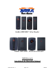
1.0 Parts List
PARTS LIST (Included) Quantity
- MI100-xxxA reader with snap-on bezel and 3 meter cable. 1
- Security screw 1
- Installation manual 1
Not included parts required for installation are wire splices, linear power supply (12V, 100mA), and etc…
2.0 Mounting Instructions
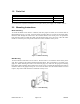
Mullion Mounting
To mount the MI100-xxxA reader to a mullion, drill two proper size holes (for 6-32 sheet metal or
thread forming screws) 3.3" apart. At center of these two holes drill a 0.375" hole for the reader cable.
Route the cable through the center hole to the controller. Remove the security screw to separate the
bezel from the reader to install the reader onto the mullion using two 6-32 screws. Once the reader
module is screwed in place, snap on the reader bezel and re-install the security screw.
Figure 1- Mullion Mounting
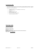
Wall Mounting
To wall mount the reader there are two choices. The first choice is to mount the reader directly to the
wall. This is similar to the mullion mounting described above. The second choice is to mount it on a
gang box. When installing the reader on an electrical gang box, make sure the gang box mounting
holes fit the reader mounting holes. Remove the security screw to separate the bezel from the reader to
install the reader to the gang box using two 6-32 screws as shown. Once the reader module is screwed
in place, snap on the reader bezel and re-install the security screw.
Figure 2 - Wall Mounting