Indala MIFARE Slim Reader Indala MIFARE Wallswitch Reader MI100-xxxA Installation & Operating Manual K02013-000 Rev.
FCC This device complies with part 15 of the FCC rules. Operation is subject to the following two conditions: (1) this device may not cause harmful interference, and (2) this device must accept any interference received, including interference that may cause undesired operation. Changes or modifications not expressly approved by the party responsible for compliance could void the user’s authority to operate the equipment.
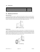
1.0 Parts List PARTS LIST (Included) - MI100-xxxA reader with snap-on bezel and 3 meter cable. - Security screw - Installation manual Quantity 1 1 1 Not included parts required for installation are wire splices, linear power supply (12V, 100mA), and etc… 2.0 Mounting Instructions Mullion Mounting To mount the MI100-xxxA reader to a mullion, drill two proper size holes (for 6-32 sheet metal or thread forming screws) 3.3" apart. At center of these two holes drill a 0.375" hole for the reader cable.
3.0 Connecting the Reader • Connect the reader to the host controller per the wiring table below and the host installation guide. Wire Color Red (input) Black (input) Drain (input) Foil Shield (input) White (output) Green (output) Blue (input) Brown (input) Orange (input) Symbol V+ VGND GND “1” “0” Name/Function Positive Supply Voltage. Return Power (Common) Line. Earth Ground. Cable Shield. Wiegand Data 1. Wiegand Data 0. Beeper Control Line. Red LED Control Line. Green LED Control Line.
Sector Read Only Mode • In Sector Read Only Mode the reader reads and outputs a specified number of bits from a specified sector based on a custom configuration of the reader. The following reader attributes can be configured at the factory to meet individual needs: 1. 2. 3. 4. 5. 6. 7.