
User's Manual
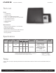
Table Of Contents

iCLASS SE
INSTALLATION GUIDE
2
PLT-01545, A.0
U90 (U90.915 & U90.865)
© 2014 HID Global Corporation/ASSA ABLOY AB. All rights reserved.
Specifications
Parts List
Parts
1 - iCLASS Reader
1 - Installation Guide
2 - #6-32 x .375” Phillips machine screws
2 - #6-32 x .375” Spanner security screw, anti-tamper
2 - 7-pin Terminal connectors
1 - 10-pin Terminal connector
1 - Mounting Gasket
1 - Back Box
recommended
• Cable, 5-9 conductor (Wiegand or clock-and-data)
• Linear DC Power supply
• Metal or plastic junction box
• Security Tool (for anti-tamper screw) HID 04-0001-03
• Drill with various bits for mounting hardware
• Mounting Hardware
UL Reference Number Deciphering
x
1
Reader Colors: K = Black
x
2
Wiring: T = Terminal
x
3
Communications: N = No Module
PRODUCT
BASE PART
NUMBER
INPUT
VOLTAGE (VDC)
CURRENT
OPERATING
TEMPERATURE
CABLE LENGTH
UL REF
NUMBER
Standby
AVG
1
Max
AVG
2
PEAK
3
U90 960N
12 VDC 320mA 400mA 1.0 A
-30° to 150° F
(-35° to 65° C)
Power Supply Lines
40 ft (12 m) - 22 AWG
100 ft (30 m) - 18 AWG
Communication Lines
Wiegand / Clock-and-Data
500 ft (152 m) - 22 AWG
RS-485
4,000 ft (1,219 m) - 24 AWG
U90Ax
1
x
2
x
3
24 VDC 160mA 200mA 0.5 A
1
Standby AVG - RMS current draw without a card in the RF eld.
2
Maximum AVG - RMS current draw during continuous card reads. Not evaluated by UL.
3
Peak - highest instantaneous current draw during RF communication.
Relays
Three (3) each dry relays for operating external audio and visual indicators. Not to be used for Access Control. Rated 30VDC, 2A
resistive.