FlexPass TM Advantage Series Proximity Plus TM ASR-620++ PowerProx TM Reader User Manual K02021-000 Rev A April 2006
FCC Compliance: This equipment has been tested and found to comply with the limits for a Class B digital device, pursuant to Part 15 of the FCC rules. These limits are designed to provide reasonable protection against harmful interference in a residential installation. This equipment generates, uses and can radiate radio frequency energy and, if not installed and used in accordance with the instructions, may cause harmful interference to radio communications.
• Maintain all reader wiring a minimum distance of 12" (30 cm) away from other wiring such as AC power, computer data wiring, telephone wiring or wiring to electric locking devices, etc. • Do not install the reader in areas where sources of broad spectrum EMI noise may be present. Examples of EMI broad spectrum noise producers are motors, pumps, generators, AC-DC converters, uninterruptable power supplies, AC switching relays, light dimmers, computer monitors and CRTs.
iv K02021-000 Rev A April 2006
1.0 Overview 1.1 Introduction The ASR-620++ reader is a rugged radio frequency reader designed for applications such as identification systems, security systems and data collection. The ASR-620++ reader mounts on most flat surfaces. The reader electronics are enclosed with a gasket sealed cover to provide weather resistance. The reader outputs data in Wiegand or ABA Track II (Mag Stripe) format.
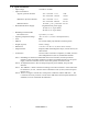
1.3 Specifications • • Input Voltage: Input Current/Power -Typical, quiescent off metal 12.0 VDC to 24 VDC. -Maximum, quiescent off metal • • • • • • • • • 2 -Maximum Power Recommended Power Supply: Vin = 12.0 VDC 1.0 A Vin = 24.0 VDC 750 mA Vin = 12.0 VDC 1.2 A Vin = 24.0 VDC 920 mA 12.0 VDC ≤ Vin ≤ 24.0 VDC Regulated linear power supply 12 VDC at 1.5 A (per reader) 24 VDC at 1.0 A (per reader) 12 W 18.0 W 14.4 W 22.1 W 22.
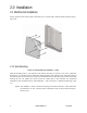
1.4 Unpacking and Identifying Supplied Parts Unpack the equipment and become familiar with the components (see Figure 2, ). The ASR-620++ package contains the ASR620++ reader electronics module, the ASR-620++ cover, and a tuning tool. Figure2a ASR-620++++ Package Contents Figure 1.
1.5 Identifying the Reader Format The reader format is printed on the ID label (see figure 3) located on the rear of the base assembly, and under the cover on one of the two metal shields. Figure 3.
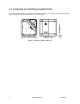
2.0 Installation 2.1 Mechanical Installation Proper operation of the reader requires mounting it on a vertical surface with the LEDs located in the top left corner. 2.1.1 Wall Mounting Figure 3. Wall mounting the ASR-620++ reader Drill the mounting holes to a #8 clearance and drill the cable hole to at least 13/16” (0.813”) diameter. Remove the cover from the base and feed the cable through the cable clearance hole. Attach the reader to the wall using #8 screws.
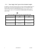
2.1.1 Power Supply Cable Types and Recommended Lengths The ASR-620++ reader requires a minimum voltage of 12.0 VDC at the reader. Voltage drops, caused by the cable resistance, can be made up by increasing the power supply voltage. DO NOT SET THE POWER SUPPLY VOLTAGE TO HIGHER THAN 28 VDC! In noisy environments, use shorter cable runs.
2.1.2 Reader to Host Interface Wire Types and Lengths Refer to Table 2 to determine the recommended wiring type at various maximum reader to host distances. Variation in distance requires different wire gauges. Because of system data termination differences, contact your system manufacturer for exact requirements. Installation should be in accordance with National Electric Code ANSI/NFPA 70. Reader Cable Length Cable Type Host Controller Panel Maximum Cable Length 22 AWG (0.
2.2 Electrical Installation 2.2.1 Grounding Connect the reader directly to an earth ground as shown in fugure 4. An earth ground can be established by driving a copper clad ground rod into the earth. Make certain the DC resistance between your established earth ground and the system ground is very low. If direct connection to a ground rod is not possible, connect the reader to an earth-ground (do not connect to fire sprinkler system), or to steel frames (building beams) that connect to earth.
2.2.2 Reader to Host Interface Wiring Figure 5 shows interfaces for Magstripe and Wiegand Host controllers. Choose the appropriate interface for your installation. (RS-232 configuration requires a BIL-422/232 Signal Conditioning Module which is sold separately.) Figure 5. Magstripe and Wiegand Reader to Host Interface Wiring Please observe the following: • The system must have a single earth ground point.
2.3 Tuning the Reader Tuning the reader is not necessary in most installations. The reader should be mounted and tested for read range and host output function prior to attempting an adjustment of the reader. Before attempting to tune the reader, call Indala Technical Support at (800) 646-3252 or (408)361-4700 for instructions.
3.0 Operation When power is first applied to the reader, it performs internal power up diagnostics. If it is functioning properly, the reader will flash the LED and beep twice. After the power up diagnostics are completed and the reader is in a READY status mode you may present a standard or option card to the reader. 3.1 Startup Diagnostic The readers have an internal diagnostic routine to assure reader operation at start-up, as well as a means to test the integrity of the data lines.
3.2 Presenting the Card Figure 7. Presenting the Card To obtain maximum read range, present the card to the reader as shown in Keeping the card parallel to the ASR-620++ reader and move it slowly toward the face of the reader until a QuickFlash is obtained. This is the point at which the card is read and the data is transmitted to the controller. To read the card again, remove it from the reader field and present it again.
3.5 Controls and Indications 3.5.1 Wiegand and Mag Stripe Single-Line Control LED Host to Reader Interface Wiring • There is no LED OFF state in this configuration.LED is red when the brown wire is high (above 2.2 VDC or not connected). • Pull brown wire low to change LED color to green. • Toggle brown line high-low at a rate of 100 Hz to 1 kHz, 50% duty cycle, to produce amber LED color. • Pull blue beeper wire low to activate audio beep tone. 3.5.
3.5.3.4 SelfTest Card This option card enables or disables the line test mode upon presentation (Indala part number 07257-001). Present the card once to put the reader into the line test mode. Present a second time to revert to normal operation. 3.5.3.5 WatchDog Enable/Disable Card This option card toggles the state of the automatic WatchDog option (Indala part number 07508-001). If one beep is heard when the card is presented to the reader, the WatchDog output is enabled.
5.0 Additional Information 5.1 Mechanical Drawings Figure 8.
5.2 Copyrights, Patents, and Trademark Credits Indala Corporation reserves all rights including patents, copyrights, trademarks, trade names, and all other intellectual property rights worldwide. No reproduction, adaptation, or translation is allowed without prior written permission from Indala Corporation. Indala Corporation reserves the right to change any product description and/or specification contained here without prior notice.