
User's Manual


K02021-000 Rev A April 2006
5
2.0 Installation
2.1 Mechanical Installation
Proper operation of the reader requires mounting it on a vertical surface with the LEDs located in the top
left corner.
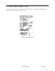
2.1.1 Wall Mounting
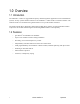
Figure 3. Wall mounting the ASR-620++ reader
Drill the mounting holes to a #8 clearance and drill the cable hole to at least 13/16” (0.813”) diameter.
Remove the cover from the base and feed the cable through the cable clearance hole. Attach the reader to
the wall using #8 screws. Insure the O-rings are installed between the mounting screw heads and the base
housing (do not over tighten the screws). Route the reader cable to the controller. For mechanical
dimensions, cable and hole location of the ASR-620++, refer to Section 5.1 (Mechanical Drawings, page
15).
NOTE: The ASR620++ reader is tuned for mounting on non-ferrous surfaces. If the reader must
be mounted on, or near, a ferrous surface a minimum 3 inch (7.6cm) non-ferrous spacer
must be used.