
User's Manual


_________________________________________________________________________________________
HID Corporation 9292 Jeronimo Road Irvine, CA 92618 USA TEL (949) 598-1600 (800) 237-7769 FAX (949) 598-1690
Web page –
www.proxtrak.com
– ProxTrak Portal Reader Installation Procedure 6042-901-01 Rev 7
26 of 32
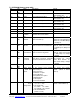
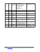
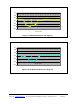
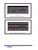
A B C D E F G H J
MiniProx 28/32 29/41 28/52 22/28 27/63 36/55 33/70 35/48 33/70
ProxPro 41/53 48/55 38/54 33/48 45/57 42/69 30/35 48/74 42/82
ProxPro+ 51/187 96/119 74/99 92/122 77/87 145/23 102/103 88/120 165/240
MaxiTrak 29/32 22/32 26/34 24/31 34/58 31/40 22/39 31/42 48/64
Portal 94/265 103/146 111/117 75/88 118/150 117/185 84/96 116/187 139/146
Figure 4-2. Interference Distances
11. Environmental Radio Frequency Noise Test
The following is a description of a test (or measurements) to be completed to ensure that the portal is
able to interact with other RFID readers.
11.1 Required Equipment
• Spectrum Analyzer (HP3585A)
• “Standard” antenna (MaxiTrak antenna) mounted on tripod with degree markings
11.2 Test Procedure
NOTE: This procedure should be performed during a normal work period, i.e. elevators or escalators
running, computer monitors running in their normal mode of operation, any access readers in the area
turned on etc.
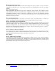
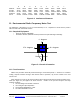
Setup tripod in the center of the proposed unit location starting with the antenna oriented towards the 0°
mark (see Figure 5-1) and approx. 42” above the floor. Connect to the spectrum analyzer and setup
analyzer as follows:
1. Set Scan Range from 80 kHz to 200 kHz
2. Use 1 Meg ohm input impedance
3. Set Resolution Bandwidth to 1 kHz
4. Set Video Bandwidth to 3 kHz
Direction of travel
0 - de
g
rees
90 - degrees270 - degrees
Figure 5-1 Portal Orientation