
User's Manual


_________________________________________________________________________________________
HID Corporation 9292 Jeronimo Road Irvine, CA 92618 USA TEL (949) 598-1600 (800) 237-7769 FAX (949) 598-1690
Web page –
www.proxtrak.com
– ProxTrak Portal Reader Installation Procedure 6042-901-01 Rev 7
18 of 32
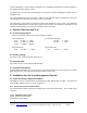
7.2 Communication Processor Switches:
Switch 6
– Read, Report modes
1. Set Tamper Latch Mode If On, set tamper latch bit. If off, Set Quiet bit.
2. Re-Report If On, Tag ID’s are always reported. If off only new tag ID’s are
reported
3. Indicator re-reports If On, Indicators report for every tag. If off only new tags are reported
4. Fast Indicator duration If On, indicators are 4X faster than default duration’s.
5. Acquisition test reports If On, Sends receiver and power level reports on serial port. (If switch
block switch 7 is on LCD will be updated ) Simplex always responds with
test data.
6. Spare Not used
7. LCD test mode If On, LCD reports ID and sensor messages, off is Host control of LCD
8. Test LCD type If On, LCD is single line, off is dual line
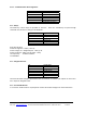
Switch 7
– Serial Settings (all off)
1. Simplex serial output (On, off) If On, Simplex Serial output
2. Baud Rate On -- 4800 On -- 9600 Off -- 38,400 Off -- 19,200
3. Baud Rate On – 4800 Off – 9600 On – 38,400 Off – 19,200
4. Node address, Bit 0 On = 1 Off = 0
5. Node address, Bit 1 On = 1 Off = 0
6. Node address, Bit 2 On = 1 Off = 0
7. Node address, Bit 3 On = 1 Off = 0
8. Node address, Bit 4 On = 1 Off = 0
Note: Data is always 8 bits, no parity, 1 stop bit
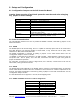
Switch 8
– Hardware options and test modes
1. MaxiTrak mode If On, Firmware is put in MaxiTrak Mode
2. FSK Exciter If On, Uses the same exciter for access and assets
3. Free Running If On, Acquisition is free-running regardless of Host polls
4. Output Port If On, LED port switches to an output port, Off is not used
5. Hardware demod. for FSK If On, FSK data has been demodulated in h/w, if off, firmware must
demodulate raw data.
6. Spare Not used
7. Spare Not used
8. Spare Not used
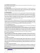
Switch 9
– Initialization and overrides
1. Switch Over-ride (On, off) If On, firmware disregards all switches and uses EEPROM
2. Reset to Factory defaults (On, off) If On, at power-up, EEPROM is set to firmware values
3. EEPROM unlock (On, off) If On, allow writes to reserved EEPROM area
4. Flash Mode bit 0 Not used
5. Flash Mode bit 1 Not used
6. Spare
7. Spare
8. Set Wiegand Facility code If On, Unit resets and assigns the facility code of the next read Access
card to an EEPROM location. This FAC code will be inserted into all
Wiegand messages.
Other System Switches:
Switch 1 - Reset switch
Switch 10 - Vandal switch
Switch 11 - Presence simulator switch
Switch 12- Exit simulator switch