
User's Manual


_________________________________________________________________________________________
HID Corporation 9292 Jeronimo Road Irvine, CA 92618 USA TEL (949) 598-1600 (800) 237-7769 FAX (949) 598-1690
Web page –
www.proxtrak.com
– ProxTrak Portal Reader Installation Procedure 6042-901-01 Rev 7
17 of 32
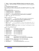
7. Tables – Switch settings, EEPROM Settings and Indicator actions
Switch Settings - Caution: Power must be off and Static protection must be used when changing these
switches.
7.1 Acquisition Processor switches
Note: In general the acquisition switches are factory and troubleshooting settings only – the Main
configuration changes are done on the Communication section Switches – Switch 6, 7, 8 and 9, shown
below.
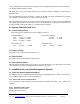
Switch 2
– Acquisition testing
1. De-multiplexed data capture Channel (Receiver) 1
2. De-multiplexed data capture Channel (Receiver) 2
3. De-multiplexed data capture Channel (Receiver) 3
4. De-multiplexed data capture Channel (Receiver) 4
5. Header capture If On, F/W allows Header from strongest channel to be at 0x80008000
6. ID Capture If On, F/W allows next ID from the strongest channel to be at 0x80008000
7. Skip auto-null If On, skips auto-null at power-up
8. Spare Not used
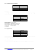
Switch 3
– Acquisition testing (continued)
1. Miller code generator If On, generates a Miller coded tag number for de-bugging purposes
2. Checksum validation If On, Reader requires a checksum for validating Asset tags
3. A/D loop-back If On, Reader generates an data stream for the digital filtering algorithms
4. Disable Dynamic Auto-null If On, Disables the dynamic auto-null
5. Run Mode If On, Forces CP Run mode ("RN" on LED's)
6. Programming mode If On, no programming on power-up, normal operating mode ("FL") on
LED's
7. Skip FSK Reader Along with switch 8 (Lsbit), it is the number of cycles skipped for the FSK mode
After a successful Access read.
8. Skip FSK Reader Along with switch 7 (Msbit), it is the number of cycles skipped for the FSK
mode, after a successful Access read.
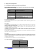
Switch 4
– Acquisition testing (continued)
1. Force I phase If On, Acquisition is always on I phase
2. Force Q phase If On, Acquisition is always on Q phase
3. 180 degree phase shift If On, data is shifted 180 degrees
4. Daughter board type Off for current daughter board
5. Daughter board type Off for current daughter board
6. Daughter board type Off for current daughter board
7. Daughter board type Off for current daughter board
8. Daughter board type Off for current daughter board
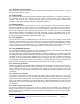
Switch 5
– Acquisition testing (continued)
1. Filter Setting If On, Band-pass filter (Used for 2D systems
2. ID averaging Along with switch 3, it is 2-to-the-nth ID's that are averaged (Lsbit)
3. ID averaging Along with switch 2, it is 2-to-the-nth ID's that are averaged (Msbit)
4. Channel for Maui detection Along with switch 5, receiver used for Maui (LSBit)
5. Channel for Maui detection Along with switch 4, receiver used for Maui (MSBit)
6. Maui enable If On, Maui enabled
7. Force Maui threshold If On, Sets Maui threshold to 0x40
8. Single Tag Mode If On, Only one Asset read per cycle to improve speed