
Installation Manual

HID Corporation 9292 Jeronimo Road Irvine, CA 92618 USA TEL (949) 598-1600 (800) 237-7769 FAX (949) 598-1690
Web page, E-mail - www.prox.com AMR100 Property Pass Reader Installation Manual 6015-900 REV A 3 of 6
E4
E5
P
1
9
S
W
5
P
1
8
1
1
T
B
4
T
B
4
-
1
D
0
T
B
4
-
2
D
1
T
B
4
-
3
D
2
T
B
4
-
4
D
3
T
B
4
-
5
D
4
T
B
4
-
6
D
5
T
B
4
-
7
D
6
T
B
4
-
8
D
7
T
B
4
-
9
+
V
T
B
2
T
B
2
-
1
T
D
T
B
2
-
2
R
D
T
B
2
-
3
S
I
G
N
A
L
R
T
N
T
B
2
-
4
4
8
5
+
T
B
2
-
5
4
8
5
-
T
B
2
-
6
S
I
G
N
A
L
R
T
N
T
B
2
-
7
R
E
L
A
Y
1
N
/
C
T
B
2
-
8
R
E
L
A
Y
2
N
/
O
T
B
2
-
9
R
E
L
A
Y
1
C
O
M
M
T
B
2
-
1
0
R
E
L
A
Y
2
N
/
C
T
B
2
-
1
1
R
E
L
A
Y
2
N
/
O
T
B
2
-
1
2
R
E
L
A
Y
2
C
O
M
M
T
B
3
T
B
3
-
1
R
T
N
1
T
B
3
-
2
+
5
V
T
B
3
-
3
I
N
T
T
B
3
-
4
R
S
T
B
3
-
5
R
/
W
T
B
3
-
6
E
N
T
B
3
-
7
G
R
E
E
N
O
U
T
T
B
3
-
8
R
E
D
O
U
T
T
B
3
-
9
B
E
E
P
O
U
T
T
B
3
-
1
0
R
T
N
2
T
B
1
T
B
1
-
1
D
A
T
A
0
T
B
1
-
2
D
A
T
A
1
T
B
1
-
3
C
A
R
D
P
R
E
S
E
N
T
T
B
1
-
4
D
A
T
A
R
T
N
T
B
1
-
5
G
R
E
E
N
I
N
T
B
1
-
6
R
E
D
I
N
T
B
1
-
7
B
E
E
P
I
N
T
B
1
-
8
H
O
L
D
T
B
1
-
9
T
A
M
P
E
R
T
B
1
-
1
0
C
O
M
M
O
N
T
B
5
T
B
5
-
1
+
D
C
T
B
5
-
2
S
H
I
E
L
D
T
B
5
-
3
G
R
O
U
N
D
T
B
4
-
1
0
R
T
N
3
TB5
1
P2
1
P1
1
P41
P17
1
3
TB3
TB4
TB1
TB2
SW1
R5
SW2 SW3 SW4
SW6
P12
P14
P8P5
P3
P16P24
1
11
1
1
1
1 1
1
1
1 1
1 1
111
1 1
1
1
1
1
P
7
P
1
0
P
1
1
P
1
5
P
1
3
P
2
0
P9P6
A
3.28
5.25
8.00
8.00
12 PLCS, .156
STARTER HOLES
FOR WALL MOUNT
SW1
SW2
SW3
SW4
1
1 1
P6
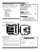
Figure 5
Mounting
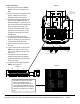
1. Mount the base of the AMR100 Property Pass Reader
to the prepared surface using the starter holes indicated
in Figure 2.
2. These holes are not through holes and require drilling
before mounting.
3. Choose the holes to be used and drill with a 5/32 (.156)
inch bit. Use #6 screws only.
O-Ring
1. After the AMR100 Reader base is mounted, install the
rubber o-ring by stretching around the reader base and
placing it in the groove located along the edge. See
Figure 2 for details.
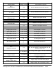
Switch Settings
Set the DIP Switches labeled Switch 1 - Switch 4
(Figure 5) according to the following tables.
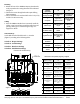
Switch #1 - Report Settings
Switch #2 - Serial Settings
Switch #3 - Hardware Settings
Switch #4 - Initialization Settings
* Denotes the default setting.
Note: Data is always 8 bits, no parity, 1 stop bit
A
SWITCH #1
Report Settings
ON OFF
1
Set Tamper Latch Mode
*Tag command is "Set
Tamper"
Tag command is read
from EEPROM
2
Re-report ID's
*Tag ID's are re-
reported on each Poll
Reports only ID's that
are different from
previous
3
Indicator re-report
*Indicators activate for
every ID
Indicators activate only
for different from
previous
4
Fast indicator duration's
Use 4X faster indicator
durations
*1X durations
5
Acquisition test reports
Sends receiver and
power level test reports -
effects Simplex output
and LCD
*
6
EPP Database
*
7
LCD Reports
LCD reports ID and
sensor messages
*Host only control of
LCD
8
Test LCD
Test
*LCD. For factory use
only
SWITCH #1
Report Settings
ON OFF
1
Set Tamper Latch
Mode
*Tag command is
"Set Tamper"
Tag command is
read from
EEPROM
2
Re-report ID's
*Tag ID's are re-
reported on each
Poll
Reports only ID's
that are different
from previous
3
Indicator re-report
*Indicators activate
for every ID
Indicators activate
only for different
from previous
4
Fast indicator
duration's
Use 4X faster
indicator durations
*1X durations
5
Acquisition test
reports
Sends receiver and
power level test
reports - effects
Simplex output and
LCD
*
6
EPP Database
*
7
LCD Reports
LCD reports ID and
sensor messages
*Host only control
of LCD
8
Test LCD
Test
*LCD. For factory
use only