
Installation Manual

HID Corporation 9292 Jeronimo Road Irvine, CA 92618 USA TEL (949) 598-1600 (800) 237-7769 FAX (949) 598-1690
Web page, E-mail - www.prox.com AMR100 Property Pass Reader Installation Manual 6015-900 REV A 2 of 6
E4
E5
P
1
9
S
W
5
P
1
8
1
1
T
B
4
T
B
4
-
1
D
0
T
B
4
-
2
D
1
T
B
4
-
3
D
2
T
B
4
-
4
D
3
T
B
4
-
5
D
4
T
B
4
-
6
D
5
T
B
4
-
7
D
6
T
B
4
-
8
D
7
T
B
4
-
9
+
V
T
B
2
T
B
2
-
1
T
D
T
B
2
-
2
R
D
T
B
2
-
3
S
I
G
N
A
L
R
T
N
T
B
2
-
4
4
8
5
+
T
B
2
-
5
4
8
5
-
T
B
2
-
6
S
I
G
N
A
L
R
T
N
T
B
2
-
7
R
E
L
A
Y
1
N
/
C
T
B
2
-
8
R
E
L
A
Y
2
N
/
O
T
B
2
-
9
R
E
L
A
Y
1
C
O
M
M
T
B
2
-
1
0
R
E
L
A
Y
2
N
/
C
T
B
2
-
1
1
R
E
L
A
Y
2
N
/
O
T
B
2
-
1
2
R
E
L
A
Y
2
C
O
M
M
T
B
3
T
B
3
-
1
R
T
N
1
T
B
3
-
2
+
5
V
T
B
3
-
3
I
N
T
T
B
3
-
4
R
S
T
B
3
-
5
R
/
W
T
B
3
-
6
E
N
T
B
3
-
7
G
R
E
E
N
O
U
T
T
B
3
-
8
R
E
D
O
U
T
T
B
3
-
9
B
E
E
P
O
U
T
T
B
3
-
1
0
R
T
N
2
T
B
1
T
B
1
-
1
D
A
T
A
0
T
B
1
-
2
D
A
T
A
1
T
B
1
-
3
C
A
R
D
P
R
E
S
E
N
T
T
B
1
-
4
D
A
T
A
R
T
N
T
B
1
-
5
G
R
E
E
N
I
N
T
B
1
-
6
R
E
D
I
N
T
B
1
-
7
B
E
E
P
I
N
T
B
1
-
8
H
O
L
D
T
B
1
-
9
T
A
M
P
E
R
T
B
1
-
1
0
C
O
M
M
O
N
T
B
5
T
B
5
-
1
+
D
C
T
B
5
-
2
S
H
I
E
L
D
T
B
5
-
3
G
R
O
U
N
D
T
B
4
-
1
0
R
T
N
3
TB5
1
P2
1
P11
P41
P17
1
3
TB3
TB4
TB1
TB2
SW1
R5
SW2 SW3 SW4
SW6
P12 P14
P8P5
P3
P16
P24
1
11
1
1
1
1 1
1 1
1 1
1 1
111
1
1
1
11
1
P
7
P
1
0
P
1
1
P
1
5
P
1
3
P
2
0
P9P6
A
3.28
5.25
8.00
8.00
12 PLCS, .156
STARTER HOLES
FOR WALL MOUNT
CABLE STRAIN RELIEF NUT
BASE
SCREW
O-RING
COVER
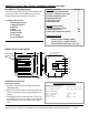
Cable Preparation
1. Route the cable from the AMR100
Reader and/or power supply to the
Host.
2. Prepare the cable by cutting the jacket
back 2" and strip the wires 1/4".
Tinning the wires is not required.
3. Install the cable strain relief nut #1 on
the rear of the AMR100 Reader as
indicated in Figure 2 . (Strain relief nut
#2 is for use with the LCD display unit
that is purchased separately. If no
LCD unit is being used and a water
tight seal is necessary, place a cable
segment into the strain relief nut #2
and tighten it)
4. Connect the Reader to the Host
according to the terminal description in
Figure 4. Do not leave extra loops of
wire inside the Reader housing.
5. Tighten the strain relief nut to secure
the cable.
6. Connect the drain line of the shield to
TB5-2. (See Figure 3 ) If it is bare,
sleeve it to avoid short circuits to the
other wires.
7. The opposite end of the drain line
should be connected to the negative
terminal and the frame connections of
the power supply.
8. Connect the power supply ground to
TB5-3. (See Figure 3 )
Figure 2
TB5
1
TB3
TB4
TB1
TB2
1
1
1
1
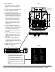
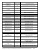
Figure 3
This label is located on the inside
base of the AMR100 Reader. It
shows all the terminal connections
for interfacing the AMR100 Property
Pass Reader with the Host. TB3 and
TB4 are for use with the LCD add-on
unit.
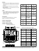
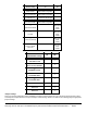
Figure 4
1
2
1
2
A