
User's Manual


__________________________________________________________________________________________________________
HID Corporation, 9292 Jeronimo Road, Irvine, CA 92618-1905, USA •Tel: (949) 598-1600, (800) 237-7769, Fax: (949) 598-1690
http://www.hidcorp.com MaxiProx Reader Installation Manual 5375-900 REV 06
Page
5
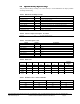
Table 8: Switch Description - SW5
Switch Default Description
1. Data Isolation 1 On See 1 below
2. Data Isolation 0 On See 1 below
3. RS422 Terminating Resistor On See 5 below
4. Serial Hardware line setting 1 Off See 6 below
5. Serial Hardware line setting 2 Off See 7 below
1. Open Collector Data Outputs SW5-1&2 when using Wiegand or Clock & Data Interface. The data
outputs may be configured so the MaxiProx is electrically isolated from the Host pull-up resistors. The
default (standard) configuration is non-isolated outputs, switches SW5-1 & 2 are
ON.
Note
When the outputs are configured as isolated, separate power supplies should be used for the MaxiProx and
Host. These switches are unused when in RS232 or RS422 mode.
3. Beeper Control SW1-4: The on-board beeper may be enabled or disabled. When enabled, the beeper
tone is sounded when the LED is green. SW1-4 in the
ON position enables the beeper (the default).
2. LED Control SW1-5: The LED flash after valid card read can be controlled by both the MaxiProx and
Host, or Host only. SW1-5 in the
OFF position selects flash green after valid card read (the default).
4. LED Mode SW1-6: Single/Dual Mode. With SW1-6 OFF (default) it is in Single Mode. The LED is
normally red, until internal or host control turns it green (only a single control line is necessary). If
ON, it
is in Dual Mode, and the LED is normally off (two control lines are necessary for host control of red and
green).
5. SW5-3 Terminating Resistor: Some RS422 connections require that the RX- line be terminated with
a resistor to RX+. If SW5-3 is in the
OFF position, there is no terminating resistor on RX-. If SW5-3 is
ON, then a 120-ohm resistor is connected between RX+ and RX-.
6. SW5-4 Line Setting 1: SW5-4 is used to configure the Reader's interface configuration. SW5-4 should
be in the
OFF position for RS232 or RS422 operation.
7. SW5-5 Line Setting 2: SW5-5 is used to configure the Reader's interface configuration. SW5-5 should
be in the
OFF position for RS232 or RS422 operation.
2.9
2.9 2.9
2.9 Tamper Switch
Tamper SwitchTamper Switch
Tamper Switch
Connect the tamper switch to the Host, if provided by the Host. When the cover is removed, the tamper
switch is released. The switch contacts available on TB1 Pins 4 and 5 and are either "normally open" or
"normally closed" dependent upon the position of the jumper on P1. Install the jumper to connect pins 1 and
2 if you need the "normally open" contacts. Select the 2-3 position if you need the "normally closed"
contacts. "Normally closed" refers to the condition of the switch when the case is open. The contacts are
rated for 50 mA at 30 VDC.
2.10
2.10 2.10
2.10 Mounting
MountingMounting
Mounting
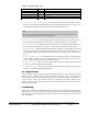
Mount the base of the MaxiProx that holds the electronics to the surface using the holes located on the base
of the Reader. There are 12 recessed holes for mounting. The holes are not through holes and require drilling
before mounting. Chose the appropriate holes to be used and drill with a 5/32 (.156) inch bit. Use #6 screws
only. (See figure 2).