
User's Manual


__________________________________________________________________________________________________________
HID Corporation, 9292 Jeronimo Road, Irvine, CA 92618-1905, USA •Tel: (949) 598-1600, (800) 237-7769, Fax: (949) 598-1690
http://www.hidcorp.com MaxiProx Reader Installation Manual 5375-900 REV 06
Page
3
7-Conductor cable is required when using the Hold function or if the ground for the MaxiProx's power
supply is not common with the ground of the Host. TB2 terminal 3, Data Return, is to be connected to the
ground of the Host. (Alpha 1296 C or equivalent).
7-Conductor cable is required when the
Hold function is used, and the power supply and Host "ground"
are separate. (Alpha 1297 C or equivalent).
A 22 AWG twisted pair, shielded, stranded cable (Belden 9330 or equivalent) is often required for the
tamper switch. Follow the recommendations of the manufacturer of the Host system. If the tamper input is
a supervised input, the "end-of-line" resistor may be mounted in the enclosure between TB1-4 and TB1-5.
The inner diameter of the cable fitting will accommodate a cable with an outer diameter of up to .260-
inches.
2.7
2.7 2.7
2.7 Cable Connections
Cable ConnectionsCable Connections
Cable Connections
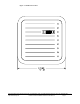
Install the cable fitting on the rear of the MaxiProx. Feed the cable through the cable fitting. Connect the
wires to the terminal strip with the minimum length necessary. Do not leave extra loops of wire inside the
Reader housing. Connect the Reader to the Host according to the terminal descriptions in the dimension
diagram. Tighten the fitting to secure the cable. Connect the drain line of the shield to terminal TB1 Pin 2
(Power Supply Shield). If it is bare, cover it with heat shrink or tape to avoid short circuits to the other wires.
The opposite end of the drain line should be connected to the negative terminal and the frame connection of
the power supply.
CAUTION!
The shunt jumper P2 is not installed as the factory default for +24VDC operation. If the jumper is in the +12
VDC position and +21 to +28.5 VDC is applied, circuit damage can result.
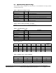
Table 1: TB1 Connector Definition
12345
+DC Shield Ground Ground
Tamper
Common
Tamper
Select
Red Drain Black --- ---
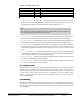
Table 2: TB2 Connector Definition
123456789
DATA 0
DATA/TD/RX
+
DATA 1
CLK/RD/RX-
DATA RTN GREEN LED RED LED BEEPER
HOLD/
CARD PRESENT
TX+
RS422
TX-
RS422
Green White Orange Brown Yellow Blue
Note
On TB2, pins 1, 2 and 7 have multiple purposes, depending on the interface that the Reader is configured for.
In the table above, the first description is for Wiegand, the second for Clock and Data, the third for RS232, and
the fourth is for RS422.