
User's Manual


__________________________________________________________________________________________________________
HID Corporation, 9292 Jeronimo Road, Irvine, CA 92618-1905, USA •Tel: (949) 598-1600, (800) 237-7769, Fax: (949) 598-1690
http://www.hidcorp.com MaxiProx Reader Installation Manual 5375-900 REV 06
Page
1
Chapter 1 MaxiProx System Overview
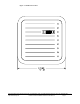
The MaxiProx Reader is a self-contained proximity Reader. The two piece polycarbonate enclosure has an
O-ring that weather seals the enclosure pieces together and a cable fitting that seals the cable entry. The
water-resistant unit is designed for outdoor use. The enclosure is mountable on a single gang electrical box.
A bi-color LED and audible tone provide user feedback. Configurable open collector data outputs provide
the data to the Host. Configurable DIPswitches and jumpers provide choice of data interfaces between
Wiegand,
Clock and Data, RS 232 and RS422. The data interface is configured as ordered from the factory,
but can be changed in the field - please contact
HID Technical Support for assistance. A tamper switch can
alert the Host when the enclosure is opened.
Internal DIP switches and jumpers provide for configuration of
the outputs, audible tone and LED control options. Installation of the MaxiProx Reader consists of
mounting, connecting the cable to the Host and +12VDC or +24VDC power, verifying the DIPswitch and
jumper settings, verifying Autotune, and verifying the reading of a transponder.
1.1
1.1 1.1
1.1 Operation
OperationOperation
Operation
Transponders (Proximity Cards or ProxKeys) are presented to the front of the MaxiProx. The LED is red
when ready to read a transponder. The LED turns green and the beeper sounds when the transponder is read
and the message is transmitted to the Host computer or interface panel. The system is ready for another
transponder as soon as the LED returns to
red. There is an anti-passback delay of about one and a half
seconds before it will read the same card. The LED flash is typically 250 milliseconds long. The operation of
the LED and beeper may be controlled by the Host, in which case the actual operation will depend on the
programmed timing of the Host.
1.2
1.2 1.2
1.2 Parts List
Parts ListParts List
Parts List
1.
MaxiProx Reader Qty 1 (included)
2. Installation Manual Qty 1 (included)
3. Cable Fitting Qty 1 (included)
4. Label for front cover - HID logo Qty 1 (included)
5. #6-32 x 1" flat head screw, for upper-left base mount screw Qty 1 (included)
6. #6-32 x 1" black screw, for gang-box mounting Qty 2 (included)
7. #6-32 x .75" flat head screw, for front cover mounting Qty 1 (included)
8. Cable, 5 conductor, 22 AWG (Alpha 1295 C or equivalent) See cable notes
9. Power Supply – 2.0 A linear regulated
+24VDC, nominal (+21 to +28.5VDC)
Factory Default – No P2 Shunt Jumper
10. +12VDC Shunt Jumper – P2-1 to P2-2 for 12VDC operation +12VDC, nominal (+11VDC to +20VDC)
1.3
1.3 1.3
1.3 Regulatory Approvals and Certifications
Regulatory Approvals and CertificationsRegulatory Approvals and Certifications
Regulatory Approvals and Certifications
Underwriters Laboratories listing
FCC Certification
Foreign Countries EMC and/or Type Approvals
CE Mark
European Declaration of Conformity