
User's Manual


__________________________________________________________________________________________________________
HID Corporation, 9292 Jeronimo Road, Irvine, CA 92618-1905, USA •Tel: (949) 598-1600, (800) 237-7769, Fax: (949) 598-1690
http://www.hidcorp.com MaxiProx Reader Installation Manual 5375-900 REV 06
Page
14
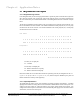
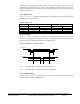
Figure 4: Data Timing - Timing Chart
1
000
1
11
00000
1111
0000
bit time strobe width
card present
data
clock/
strobe
1st valid bit
Note: the first 25 bits and trailin
g
bits are zeros, not shown above.
bit time = 1.5ms (default)
strobe width = bit time/3 (33% of bit time), default = 500us
Clock/Strobe is valid 1.5ms (one clock cycle, min) after card present is asserted
Data is valid 10us (min) before the negative edge of clock/strobe
Card Present returns to the high level 50 ms (max) after the last clock/strobe.
The above timing is representative of a magnetic stripe card traveling at 8.9 inches per second. The timing is
to be adjustable for cards traveling at 4 inches per second to 20 inches per second. This relates to bit times of
3.3 ms and 666us, respectively. There are 75 bits per inch on Track 2.
4.2.3
Output signal Levels
Inputs: low threshold = 0.8 volts high threshold = 3.5 volts
4.2.4
Bit structure
The Reader will read an 1849 or compatible chip that is encoded with 44 bits of data. The data will be
programmed in accordance with ProxGuard formatting. The data will be packed into the ABA/ISO Track 2
message format in accordance with the following rules based on customer code:
Case 1:
Customer Code = 0, 1, 63, 72, 73 or other, will have the data output as follows.
The output is in the Track 2 character format but the bits are packed in sets of three bits (octal):
ccc CCCC a bcd efg hij klm nop qrs tuv wxy zAB CDE FGH IJK
Where cccCCCC is the customer code, abc...IJK is the programmed data on the card.