
User's Manual


__________________________________________________________________________________________________________
HID Corporation, 9292 Jeronimo Road, Irvine, CA 92618-1905, USA •Tel: (949) 598-1600, (800) 237-7769, Fax: (949) 598-1690
http://www.hidcorp.com MaxiProx Reader Installation Manual 5375-900 REV 06
Page
12
The voltage, current, and timing of the data pulses are measured at the Reader in reference to the power
supply/signal ground at the Reader. The voltage, current and timing of a signal driving an auxiliary input
device on a Reader is measured at the control panel that is controlling the input device (with reference to the
signal ground at the panel).
4.1.3
Signal Levels
The Data One, Data Zero, and LED Control conductors connect signals between the Reader and the panel.
The logic levels are defined as follows:
Table 9: Logic Levels
Voltage Data Outputs (Data0 and Data1) Control Inputs (LED’s, Hold, Beeper)
Levels Minimum Maximum Minimum Maximum
Voh 3.5V 5.5V 3.5V 5.5V
Vol 0.0V 0.5V 0.0V 0.5V
Ioh 0.0mA 5.0mA -1.0mA 0.0mA
Iol -25.0mA 0.0mA 0.0mA 25.0mA
4.1.4 Data Pulses
The Data One and Data Zero signals are normally held at a logic high level until the Reader is ready to send
a data stream. The Reader places asynchronous low pulses on the appropriate data lines to transmit the data
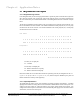
stream to the panel. The following timing parameters shall be observed:
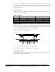
Figure 3: Data Pulses - Timing Parameters
Tpw Pulse Width Time - 30uS (minimum) to 50uS (maximum)
Tpi Pulse Interval Time - 1.8mS (minimum) to 2.2mS (maximum)
4.1.5 Example Output
The following is an example of an ID card with the number of “816” decimal, which will be output by the
MaxiProx Reader, the number “02004CA0661” hex.
Data One
Data Zero
Tpw Tpw
Tpw TpiTpi
Voh
Voh
Vol
Vol