
User's Manual


____________________________________________________________________________________________
HID Corporation 9292 Jeronimo Road Irvine, CA 92618 USA TEL (949) 598-1600 (800) 237-7769 FAX (949) 598-1690
Web page, E-mail -www.hidcorp.com ProxPro Reader Installation Manual 5355A-900 Rev M 2 of 11
ProxPro Reader™ Wiegand/Clock-Data Installation Manual
System Overview
The ProxPro reader is a self contained proximity reader. The two piece polycarbonate enclosure has an rubber
Gasket that seals the pieces together and a cable fitting that seals the cable entry. The water resistant unit is
approved for outdoor use. The enclosure is designed to fit on a single gang electrical box. A Bi-color LED and
audible tone enhance user feedback. A tamper switch feature is available that will alert the Host when the
enclosure is opened. An internal DIP switch makes the configuration of the outputs, audible tone, keypad and
LED control options simple.
Installation of the ProxPro reader consists of mounting, verifying the DIP switch settings, setting a tuning jumper
and connecting the cable to the Host.
Operation
Access Cards may be presented to either the front or the back of the reader. Optimum read range is achieved
when the access card is presented face on, and parallel to the reader face. The LED is normally controlled by
the internal reader firmware. Alternatively, the LED can be controlled by the access control host panel. When
the LED is controlled directly by the reader, the LED normal state is red, and indicates that the reader is ready
to read an access card. The LED turns green when the access card is read and the message is transmitted to
the Host system. When the reader is ready for another access card, the LED returns to red. The typical time
the LED is green is 250 milliseconds . The reader only controls the green state of the LED, there is no amber
LED state. The operation of the LED may be controlled by the Host. When the LED is host system controlled,
the LED and beeper operation may vary depending on the particular host software. The LED may then exhibit a
red, green or “amber” color for certain status conditions as controlled by that host’s software.
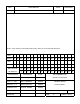
Parts List
1) ProxPro Reader qty 1 (included)
2) #6-32 x 1 self tapping screws, Type T or 23 qty 2 (included)
3) Installation Manual qty 1 (included)
4) Cable Fitting qty 1 (included)
5) Cable, 5 conductor, 22awg as required (max. 500 feet)
(Alpha 1295 C or equivalent) See cable notes.
6) Cable, 20 conductor, 22awg as required (max. 500 feet)
(Alpha 1299/20C or equivalent) See cable notes.
7) DC Power Supply 12V/100mA or 24V/120mA 1 (Installer supplied)
8) In the E.U. the recommended power supply is the Micro State Electronics Model PS-5.
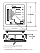
Installation Procedure
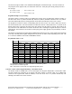
1. Determine an appropriate
mounting position
for the reader. The reader drawing below is actual size and
may be used as a template. Install a single or
double gang
electrical box or drill the appropriate mounting
for #6 fasteners. If mounting to a metal surface, drill two 7/64 (.109) inch holes and use the enclosed self
tapping screws for mounting.
2.
Route
the interface
cable
from the reader and/or power supply to the Host.
3.
Prepare the cable
by cutting the cable jacket back 2 (two) inches and strip the wires 1/4 inch. Tinning the
wires is not required.
4. Pry off the center face plate by placing a thin blade into the grove that outlines the face of the reader.
Use
care to avoid scratching the surface of the reader.
The face plate is attached to the reader by friction
only. The screws that hold the enclosure pieces together will be exposed. Loosen the four screws to open
the enclosure (the enclosure screws are captive to the cover).
5.
Install the cable
fitting on the rear of the reader. Feed the cable through the cable fitting, tighten the fitting
nut so the cable jacket is flush with the printed circuit board. Dress the cable conductors and connect the
reader to the Host according to the terminal descriptions in the dimension diagram and wiring table. The