
User's Manual


ENTRYPROX – 4045-907 REV A
18
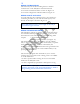
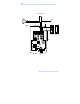
WIRING THE MAIN RELAY
The main relay for the door locking device is wired to
connector P1 on the EntryProx main circuit board.
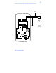
To connect a Fail-Secure Strike or Lock see Figure 12.
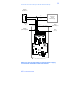
To connect a Maglock or Fail-Safe Strike see Figure 13.
WIRING A GATE ACTUATOR
You can make the wire connections for a gate actuator by
connecting the Blue (C) wire and the Green (N/O) wire
directly to the input as shown in Figure 12.
WIRING THE AUXILIARY RELAY
The EntryProx unit has an auxiliary relay feature that allows
for customized alarm programming. Pins 1, 2, and 3 on the
P2 connector can be wired for one of the following alarm
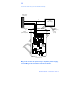
outputs: • Alarm shunt (see Figure 14)
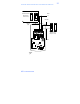
• Forced or propped door (see Figure 15)
The alarm shunt operation allows you to use the auxiliary
relay to bypass a door contact that is monitored by a separate
alarm system. If the entry or exit is controlled by the
EntryProx unit, an intrusion alarm will not be generated if the
door is opened using an access card or PIN number, or by
pressing the REX button.
The forced or propped door alarm allows you to use the
auxiliary relay to provide a local warning, such as an audible
or visual indicator if:
• A door is opened without using an access card or PIN
number at the EntryProx unit.
• A door is legitimately opened but is held open too long.
Note: DO NOT connect a power supply to the relay if
you connect a gate actuator.
Note: The auxiliary relay audible and visual indicators and
the door open times can be programmed. Refer to
Table 2:
Programming Commands
for more information.