
User's Manual


HID CORPORATION
17
WIRING ENTRYPROX
This section includes wiring diagrams for the following:
• Wiring the main relay
• Wiring the auxiliary relay
• Wiring the Request to Exit switch
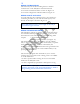
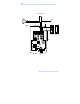
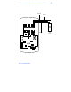
Figure 10 illustrates the location and description of the four
pin connectors on the main circuit board and its use.
FIGURE 11: PIN LOCATOR DIAGRAM
1
2
3
4
1
2
3
4
5
6
5
4
3
2
1
1
2
3
4
Blue – Not Used
Brown – Wiegand LED Control
White – Wiegand Data 1
Green – Wiegand Data 0
Green – Aux Relay NO
Gray – Aux Relay NC
Blue – Aux Relay COM
Brown – Rex Loop
Orange – Door Loop
White – Loop Common*
Red – Power +12 VDC
Black – Ground
Blue – Main Relay COM
Green – Main Relay NO
Gray – Main Relay NC
Red – LED (Red +)
Black – LED (Green +)
Antenna +
Antenna -
* Note: Rex Loop requires
NO switch; Door Loop
requires NC switch.
Connect commons from
both loops to Loop
Common input P2, Pin6,
White.