
User's Manual


HID CORPORATION
15
Request to Exit input
cable
Alpha 1292C (22AWG) or
2421C (18AWG)
Wiegand data output cable Alpha 1295C (22AWG)
Antenna cable extension Alpha 1294C (22AWG)
The cable shield drain wires must be grounded at the
reader end by connection to P1, Pin 4 (DC Power
Ground) using appropriate wire nuts or crimp fittings.
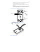
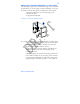
• Tamper Switch must be installed in one of the
configurations recommended below, and connected to an
intrusion alarm system. (Refer to Figure 10 for
switch/magnet locations)
MOUNTING OVER A METAL OR PLASTIC SINGLE
GANG J-BOX
1. Use an Ademco 945T magnet and reed switch (or
equivalent) with foam-backed adhesive tape.
2. Clip the screw mounting tabs from both the magnet
and reed switch using pliers or a wire cutter.
3. Remove the backing sheet from the tape on the
magnet and stick the magnet to the plastic spacer,
which is factory-installed to the back of the Keypad
board in location A (Figure 10).
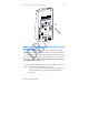
4. Stick the reed switch on the inside of the long side of
the J-box in the upper right-hand corner, using the
adhesive tape. The switch should be flush with the
edge of the J-box.
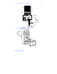
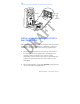
WALL MOUNTING
1. Use an Ademco PR-20451 magnet and reed switch
(or equivalent) with foam-backed adhesive tape.
2. Remove the backing sheet from the tape on the
magnet and stick the tape to the plastic spacer,
which is factory-installed to the back of the Keypad
board at location B (Figure 10).