ENTRYPROX 4045-907 (Rev A) ’S GUIDE HID Corporation 9292 Jeronimo Road Irvine, California 92618 USA Tel 949.598.1600 800.237.7769 Fax 949.598.1690 www.HIDCorp.
ii ENTRYPROX – 4045-907 REV A
iii Introduction ............................................. 1 Product Overview ................................... 2 Unit Capacity.........................................................2 Transactions .........................................................2 Specifications........................................................3 Default Settings.....................................................4 Installing Entryprox................................. 4 Assembly Parts .................................
iv ENTRYPROX – 4045-907 REV A
1 INTRODUCTION This EntryProx User’s Guide provides basic information and instructions for installing, wiring, and programming the EntryProx unit. IMPORTANT • • • • • YOU MUST KEEP A USER LIST when programming cards and PIN codes into your EntryProx. Write down the User Location, Card Number, PIN Code and the Name of the User. Use the blank form in Appendix A as a photocopy master. DO NOT PROGRAM A CARD OR PIN IN USER LOCATION 1 for normal access control use.
2 PRODUCT OVERVIEW The EntryProx unit provides card and keypad access control for a single entrance. The unit can be installed in a standard one-stage configuration or a secure two-stage (remote) configuration. (Secure installation will be card-only.) To gain access to the controlled door, the user presents their card to the reader and / or enters their PIN code into the keypad. The unit searches its memory for that card or PIN code.
3 PRE-PROGRAMMING THE UNIT BEFORE INSTALLATION Dealers and installers are advised to pre-program the unit at their offices before installing it at the site. Simply connect it to a 12VDC source, follow configuration and card enrollment instructions at the end of this guide, and disconnect the unit. Programming will be retained in memory. You will spend less time at the site, and by being familiar with programming, will be able to train the end user more effectively.
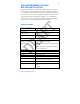
4 DEFAULT SETTINGS The EntryProx unit is shipped with the following default settings.
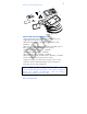
5 FIGURE 1: FACTORY SUPPLIED PARTS A K L H I B J G F D E C INSTALLER SUPPLIED PARTS LIST • Appropriate DC power supply (10-15VDC, linear type) • Appropriate electrical tools • Recommended remote antenna cable ALPHA 1294C (22AWG) • Wiegand interface cable ALPHA 1295C (22AWG) (only if using a separate Wiegand access control panel) • Power supply cable (18AWG - 22AWG) • Door lock cable (18AWG - 22AWG) • Door monitor cable (18AWG - 22AWG) • Request to Exit cable (ALPHA 2421C 18AWG or ALPHA 1292C 22AWG)
6 MOUNTING THE ENTRYPROX UNIT If you mount the EntryProx unit to a wall, you can install an electrical junction box to hold the unit and the wires in place. The mounting hole cutouts on the backplate line up with the screw holes on a standard junction box. If you mount the EntryProx unit to a glass surface DO NOT remove the wire exits on the backplate. Remove the appropriate wire exit cutouts located on each side of the controller keypad case.
7 3. Remove the wire exits and mounting hole cutouts from the backplate as shown in Fig. 2. 4. Pull the wires through the backplate as shown in Figure 3. 5. Attach the backplate to a wall or glass surface using the mounting screws or the self-adhesive fasteners.
8 WIRING THE CONTROLLER KEYPAD FOR A STANDARD INSTALLATION In a standard installation, the antenna housing remains installed in the controller keypad, and the complete unit is installed outside of the secured area. This is appropriate for interior doors or “low-risk” exterior installations. For compliance with the UL294 Standard, additional installation requirements must be met – see page 14. To wire the EntryProx unit for a standard installation, refer to Figure 4 and follow these instructions. 1.
9 FIGURE 4: REMOVING THE CIRCUIT BOARD WIRING THE CONTROLLER KEYPAD FOR A SECURE INSTALLATION In a secure installation, the waterproof antenna housing is removed from the controller keypad and mounted outside of a secured area. The control unit is installed inside the secured area. The blank filler piece is then inserted into the controller keypad in its place. This is appropriate for exterior doors or “high-risk” locations.
10 2. Remove the main circuit board by pushing outward on the two spring tabs in the direction shown in Figure 4. 3. Lift the main circuit board. 4. Unplug the four-pin cable assembly from connector P4 on the main circuit board. 5. Release the antenna housing from the controller keypad by pressing inward on the four securing tabs. 6. Remove the antenna housing from the controller keypad by pushing forward as shown in Figure 6. 7. Insert the extra 10-inch antenna cable assembly into connector P4. 8.
11 FIGURE 5: REMOVING THE P4 CONNECTOR P4 Connector Cable Assembly FIGURE 6: REMOVING THE ANTENNA HOUSING HID CORPORATION
12 MOUNTING AND WIRING THE ANTENNA HOUSING FOR A SECURE INSTALLATION Mount and wire the antenna housing no more than 10 feet away from the controller keypad unit. To mount and wire the antenna housing, refer to Figures 7 and 8 and follow these instructions. 1. Pull the additional antenna cable through the antenna housing’s backplate cable holes. FIGURE 7: MOUNTING THE ANTENNA BACKPLATE Cable Holes Moisture Release Holes 2.
13 SELECTING A FILLER OR REQUEST TO EXIT LABEL The filler piece replaces the antenna housing on the controller keypad when you use the high security installation. If you do not plan to use the filler piece as a Request to Exit switch: 1. Insert the filler piece into the opening on the controller keypad. 2. Apply the blank label. FIGURE 8: ATTACHING THE ANTENNA HOUSING If you plan to use the filler piece as a Request to Exit switch: 1. Remove the two plastic side tabs on the filler piece. 2.
14 FIGURE 9: USING THE FILLER PIECE AS A REQUEST TO EXIT SWITCH Cushion Side Tab INSTALLATION REQUIREMENTS FOR UL 294 COMPLIANCE The EntryProx Model 4045AGU00 complies with the UL294 Standard for access control units in a standard, wall-mount installation, when installed to the following specifications: • Electric locking mechanisms may only be connected to the NO contacts of the Main Relay.
15 Request to Exit input cable Wiegand data output cable Antenna cable extension • Alpha 1292C (22AWG) or 2421C (18AWG) Alpha 1295C (22AWG) Alpha 1294C (22AWG) The cable shield drain wires must be grounded at the reader end by connection to P1, Pin 4 (DC Power Ground) using appropriate wire nuts or crimp fittings. Tamper Switch must be installed in one of the configurations recommended below, and connected to an intrusion alarm system.
16 3. Drill a 3/8 inch hole in the wall behind the magnet location, feed the switch wire through the wall and press the switch into place. FIGURE 10 – TAMPER SWITCH INSTALLATION Magnet M agnetB B Magnet A M agnet A Keypad Keypad Electronics Board Electronics Board Batt. Batt.
17 WIRING ENTRYPROX This section includes wiring diagrams for the following: • Wiring the main relay • Wiring the auxiliary relay • Wiring the Request to Exit switch Figure 10 illustrates the location and description of the four pin connectors on the main circuit board and its use.
18 WIRING THE MAIN RELAY The main relay for the door locking device is wired to connector P1 on the EntryProx main circuit board. To connect a Fail-Secure Strike or Lock see Figure 12. To connect a Maglock or Fail-Safe Strike see Figure 13. WIRING A GATE ACTUATOR You can make the wire connections for a gate actuator by connecting the Blue (C) wire and the Green (N/O) wire directly to the input as shown in Figure 12. Note: DO NOT connect a power supply to the relay if you connect a gate actuator.
19 FIGURE 12: ELECTRIC STRIKE (FAIL SECURE WIRING DIAGRAM) STRIKE (Fail Secure) V- V+ BLACK (V-) GREEN (Main Relay NO) Linear type 12VDC Power Supply BLUE (Main Relay C) RED (V+ IN) Strike can also be powered by a separate power supply; consult strike installation manual for details.
20 FIGURE 13: MAGLOCK (FAIL SAFE WIRING DIAGRAM) MAG LOCK (Fail Safe) VV+ BLACK (V-) GRAY (Main Relay NC) Linear type 12VDC Power Supply BLUE (Main Relay C) RED (V+ IN) Mag Lock can also be powered by a separate power supply; consult Mag Lock installation manual for details.
21 FIGURE 14: WIRING AUXILIARY RELAY FOR ALARM SHUNT OPERATION DOOR CONTACT (Monitored by Alarm Panel) BLUE (C) ORANGE GREEN (NO) DOOR CONTACT (Monitored by EntryProx Unit) WHITE HID CORPORATION
22 FIGURE 15: WIRING AUXILIARY RELAY FOR PROPPED/FORCED DOOR ALARM POWER SUPPLY V- V+ BLUE (C) ORANGE GREEN (NO) DOOR CONTACT (Monitored by EntryProx Unit) WHITE ENTRYPROX – 4045-907 REV A
23 WIRING THE REQUEST TO EXIT INPUT When the EntryProx Request to Exit (REX) input receives a momentary switch closure, it engages the main relay for the programmed access time. It can be connected to a wallmounted exit button, to a push button under a reception desk, or to the relay output of a passive infrared motion detector mounted above the door on the secure side.
24 FIGURE 16: WIRING REQUEST TO EXIT INPUT (WITH DOOR CONTACT) ORANGE BROWN NORMALLY OPEN SWITCH WHITE DOOR CONTACT ENTRYPROX – 4045-907 REV A
25 FIGURE 17: WIRING REQUEST TO EXIT INPUT (NO DOOR CONTACT) ORANGE BROWN WHITE HID CORPORATION NORMALLY OPEN SWITCH
26 PROGRAMMING ENTRYPROX IMPORTANT – READ BEFORE PROGRAMMING THE ENTRYPROX UNIT YOU MUST KEEP A USER LIST when programming cards and PIN codes into your EntryProx. Write down the User Location, Card Number, PIN Code and the Name of the User. Use the blank form at the end of this book as a photocopy master. You will need this information if you need to delete a card or PIN at a later time.
27 LED INDICATION DURING PROGRAM MODE A slow blinking yellow LED indicates that the unit is in program mode. When the yellow LED stops blinking and is OFF completely, the unit is no longer in program mode.
28 PIN CODE/CARD PROGRAMMING BASICS PIN codes and card numbers can be programmed manually via the keypad. Cards can also be programmed by presentation to the reader at the correct point in the command sequence. When adding or modifying PIN codes or cards the user enters a 2-digit Command, then specifies three or four data values: a user type, a location and a keypad-PIN, and/or card. USER LOCATIONS These are the locations in the unit’s memory where Card and/or PIN User data is stored.
29 via the IR LED. (There are three LEDs on the top of the unit - the IR LED is the one on the right.) This code cannot be used to gain access through the door. Note that the log is only printed, not erased. Lockout (3) For this user-type, the keypad “freezes,” disallowing all other codes, plus the door remains in the current state. During a lockout state, card access does not continue to work. If it is locked, it remains locked.
30 CARD/PIN PROGRAMMING SEQUENCES Following are the most commonly used command sequences for programming user data into the EntryProx: PROGRAMMING PIN + CARD To program a user for both Code AND Card: 1. Place the EntryProx unit in program mode. Press: 99 # Master Code * (default is 1234) 2. On the EntryProx keypad, press: 50 # user-type # user location # keypad PIN * keypad PIN * 3.Press * to exit program mode.
31 PROGRAMMING CARD ONLY USE To program Card ONLY use with Command 50, simply omit the keypad PIN values from the sequence: 1. Place the EntryProx unit in program mode. Press: 99 # Master Code * (default is 1234) 2. On the EntryProx keypad, press: 50 # user-type # user location # ** 3. Press * to exit program mode. PROGRAMMING CODE OR CARD To program a user for either Code OR Card: 1. Place the EntryProx unit in program mode. Press: 99 # Master Code * (default is 1234) 2.
32 If the Batch Loading conditions can be met: 1. Place the EntryProx unit in program mode. Press: 99 # Master Code * (default is 1234) 2. On the EntryProx keypad, press: 56 # (total number of cards to be added) # (starting user location) # card number * repeat card number * NOTE: Never enter one (1) as the starting user location since it is reserved for the master code. 3.Press * to exit program mode. .
33 DELETING USERS To delete a user from the EntryProx, you must know the User Location in which the information is stored. 1. Place the EntryProx unit in program mode. Press: 99 # Master Code * (default is 1234) 2. On the EntryProx keypad, press: user location #** 3. Press * to exit program mode. BLOCK DELETE USERS Use Command 58 to delete all cards / PINs in a block of User Locations. The yellow LED will blink rapidly during the deletion process.
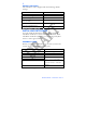
34 CHANGING OPERATING PARAMETERS Many users will use the EntryProx with the factory default operating parameters. The following commands include some of the most commonly customized parameters. For further refinements on EntryProx operation, review the options shown in Table 2. CHANGING THE MAIN RELAY TIME The main relay time applies to all users 1-2000. The factory default main relay time is five (5) seconds.
35 The Invalid PIN Lockout function disables all keypad PIN entries with the exception of the [ 99 # Master Code* ] sequence for the duration of the lockout.
36 1. Place the EntryProx unit in program mode. Press: 99 # Master Code * (default is 1234) 2. Press: 46 # 00000 # 00000 # ** 3. Press * to exit program mode. TURNING KEYPRESS AUDIBLE FEEDBACK ON/OFF The Keypress Audible Feedback command enables the sounder to beep once for each key press. This feature provides an audible acknowledgment that a particular key was pressed hard enough for the unit to understand.
37 WIEGAND MODE If you program the EntryProx unit to operate in Wiegand mode with a separate access control panel, the following features are not accessible: • The EntryProx unit does not control door lock or unlocking operations. • The EntryProx unit is not able to store codes in memory. • The main and auxiliary relay functions are turned off. • The door monitor and Request to Exit inputs are disabled.
38 PROGRAMMING COMMAND TABLE Read the following table before completing programming of your EntryProx unit; it describes various programming commands and how to execute them. As with the previously described commands, you must first press 99 # (Master Code) * to enter programming mode, enter the desired command sequence, and then press * to exit programming mode. “Ref” number is for reference only, not to provide an ordered sequence of commands. TABLE 2: PROGRAMMING COMMANDS. TO...
39 Ref IF YOU WANT TO PRESS DETAILS 7 Set/clear standard option 30 # option # s/c # ** See below for Option numbers and descriptions ESS DETAILS Option Number/Description 0: Audio keypress feature 1: Visual keypress feature 2: Auto entry enable 3: Stand-alone/Wiegand operation 4: Facility code access (26-bit cards only) 5: Forced door audio alert 6: Propped door audio alert 7: Internal Request to Exit switch 8: US/EU date format 9: Wiegand red LED enable 10: Wiegand red LED active state 11: Wiegand
40 Ref IF YOU WANT TO PRESS DETAILS 8 Print programmed user list 25 # 0 # 0# ** 9 Print programmed 25 # 0 # start user list (starting at user # ** a certain user) 10 Change Wiegand parameters Hold optional printer with IR receiver near the EntryProx IR LED. Hold optional printer with IR receiver near the EntryProx IR LED.
41 Ref IF YOU WANT TO PRESS 11 Set system time 12 Set system date 13 Set door number 14 Set propped door time (this sets delay time for both the Aux Relay and local sounder) Set forced door time (this sets active time for both the Aux Relay and local sounder) Delete memory except user list and restore system defaults (also see command 46) Delete all memory and reset system defaults 41 # hhmm # 0 hhmm = # ** hour/minute, 24-hr format 42 # mmddyy mmddyy = # dow # ** month, day, year; dow = day of w
42 Ref IF YOU WANT TO PRESS DETAILS 18 Program user: Code ONLY 50 # user-type # user location # code * repeat code * User Types: 0 - Toggle/latch strike 1 - Normal Access 2 - Log Dump 3 - Lockout 19 Program user: Code AND Card 20 Program user: Card ONLY 21 Program card user manually: Card ONLY (26-bit cards ONLY) 50 # user-type # user location # code * repeat code * 50 # user-type # user location #** 51 # user-type # user location # card ID * card ID * 22 Progra
43 Ref IF YOU WANT TO PRESS DETAILS 24 Perform batch entry of users: Card ONLY (26-bit cards ONLY) the card ID appears on the card; (facility code must be entered first; see 32 # 2 # command) 25 Block Delete Users 56 # total count # starting user location # starting card ID * starting card ID * 58 # start user # start user # number of users * number of users * 26 Quick Enroll Card 27 Print Transaction Log via IR port 28 Set transaction log mask (set/clear event logging) NED ORS HID CORPORAT
44 Code – Transaction Event 01 – Access Denied 02 – Program Denied 03 – Program Mode 04 – Request to Exit 05 – Door Ajar 06 – Door Closed 07 – Forced Door 08 – Log Erased 09 – Facility Access 16 – Print 17 – Access 20 – Toggle ON 21 – Toggle OFF 24 – Lockout ON 25 – Lockout OFF 27 – Mismatch 29 30 IF YOU WANT TO PRESS DETAILS Reset transaction Log To exit Program mode 76 # 00000 # 00000 # ** * (after final command) yellow LED stops flashing OUNDER ENTRYPROX – 4045-907 REV A
45 LED/SOUNDER STATUS INDICATIONS TABLE 3 – LED/SOUNDER INDICATIONS LED OR SOUNDER VISUAL/AUDIBLE CONDITION DESCRIPTION Yellow LED Slow blink Unit is in Program mode Verify mode is active (checking that the last two values in sequence match) Program error; to clear, press * Memory (EEPROM) erase is in progress (commands 40/46, 58 loop-back) Strike is locked Strike is energized (timed or latched) Strike toggle is unlocked and user lockout active Awaiting second form of ID during “Card AND Code” access
46 LED OR SOUNDER VISUAL/AUDIBLE CONDITION DESCRIPTION Sounder Short beep (100 ms) every 2 seconds Sounder 1/2 second on, 1/2 second off 3 rapid beeps after code is entered or card is presented 3 slow beeps (250 ms), then a single beep 1 single beep Propped door is active Forced door is active Code or Card is not found Self-test is complete Valid card access ENTRYPROX – 4045-907 REV A
47 Instructions: Do not write on this page - use it as a photocopy master. Copy the chart at a 200% enlargement. Make as many copies as required to record all programmed users, and write information in the appropriate spaces. Place the users charts in a binder, and keep them in a secure location.
48 Addendum to EntryProx Users Guide – PN 4045-907 This addendum explains what’s new in the EntryProx 4045 Rev C. The changes are: 1. Transaction History and User List downloads are no longer made via the Infrared LED to the optional HP Thermal Printer (4045-PRN). The Rev C model is compatible with the optional EntryProx DCD program, running on an optional Palm Zire 71 or Zire 72. 2. The unit now has an additional connector, P5, which provides an RS-485 interface for future applications. 3.
49 1. Install the SD Card containing the DCD Application into the Palm Expansion Card Slot. 2. Touch the Data Collection icon on the PDA screen. 3. The program will start, displaying three menu options: Retrieve, Files, and Settings 4. Click on Settings to be sure the following parameters are selected: a. Comm Method – Ir Channel 2 b. Comm Speed – 19200 c. Protocol – Printer d. Timeout (Seconds) - 30 5. To download data from the EntryProx Unit to the Palm: a.
50 2. To turn OFF an event (keep it from being stored/logged), enter: 73 # Event Code # 0 # ** To turn an event ON, enter: 73 # Event Code # 1 # ** 3. Press * to exit program mode. The Event Code is a two-digit number that represents a specific transaction as listed in the following table. The following transaction events can be set/cleared (saved/not saved) and therefore downloaded/not downloaded.
51 placing the EntryProx unit into program mode and manually entering the Display Transaction Log command.
52 PROGRAMMING A CARD OR CODE TO INITIATE A TRANSACTION LOG REPORT “DUMP” 1. Place the EntryProx unit in program mode. Press: 99 # Master Code * (default is 1234) 2. For a CODE DUMP, press: 50 # 2 # user location # code * code * For a CARD DUMP, press: 50 # 2 # user location # ** and then present the card at the proximity reader. 3. Press * to exit program mode.
53 FIGURE 18 - TRANSACTION LOG HID CORPORATION
54 The Palm PDA will store reports after they are downloaded. To view a stored report, touch Files, select a report from the list and click on Action. The drop-down menu selections are Info, View and Remove. Info gives the time and date the report was recorded. Remove allows you to delete the report. View displays the report. The top line of the screen shows the current line and total number of lines as you scroll or page up and down through the report.
55 sufficient percentage of records have been processed. The percentage of records downloaded is continually updated during the download process. 1. Place the EntryProx unit in program mode. Press: 99 # Master Code * (default is 1234)] 2. Hold the optional PDA up to the EntryProx IR port steadily (about ½ inch away; the IR port is located to the right of the yellow LED) 3. Start the DCD program on the Palm PDA, then touch Retrieve on the PDA 4.
56 Here is a description of the Report Layout: Top line – Title Second line – Session Data Column 1 – User location Column 2 – user type (see table) First letter – access modes Second letter – user types S Single PIN T Toggle function B Both code and card N Normal User E Either code or card D Download Reports (dump) L Lockout Column 3 – PIN CODE Column 4 - SITE CODE/CARD NUMBER.