
User's Manual

Installation Steps
WARNING
To prevent damage to equipment, make all
connections with power off.
1 If the reader is to be mounted on a mullion or firm flat
surface, pull an appropriate length and gauge of cable
between the host and mullion.
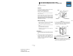
2 If the reader is to be mounted on a flat surface rather than a
handy box, use the reader base both as a template to
establish drill locations for suitable molly fasteners, etc. (not
provided), and as a guide to remove sufficient material for
wire clearance. Then pull the appropriate wire between the
host and reader location.
3. Connect the wires of the pigtail assembly to the cable end at
the reader location. Connections can be crimped or made
with twist on wire nuts.
FUNCTION W IRE COLOR
+5 to 24 VDC RED
Green LED BROWN
Data "1" /Data Output WHITE
Data "0" /Clock Output GREEN
COMMON BLACK
Buzzer YELLOW
Format Selection Switch (16 position rotary)
1 ABA mag stripe & HID prox to All Bits Wiegand
2 ABA mag stripe & HID prox to Wiegand 26 bit
3 ABA mag stripe & HID prox to Wiegand 34 bit
4 EMPI mag stripe & EMPI prox to Wiegand 26 bit
5 EMPI mag stripe & EMPI prox to Wiegand 34 bit
6 EMPI mag stripe & HID prox to Wiegand 26 bit
7 EMPI mag stripe & HID prox to Wiegand 34 bit
Following ABA only ANSI 10 or 12 (5/5 or 6/6)
8 ABA mag stripe & Proxi 10 prox to Wiegand 26 bit
9 ABA mag stripe & Proxi 10 prox to Wiegand 34 bit
4 Connect the other end of the cable to the host controller
being sure to follow the appropriate color code and wire lead
functions.
5 Verify that the cards to be read are encoded with the
selected data format.
6. Observe the reader LED; it should flash green four times as a
self-test when first powered on. If this is not the case, or it
continues with short double flashes, a problem exists, refer to
the Diagnostic Tests section.
Keypad Data
The model 240 keypad sends data keystroke-by-keystroke to
the host controller in an 8-bit (per keystroke). data format. See
Dorado by HID Application Note 20 for details.
Diagnostic Tests
The Model 230 Proximity Card Readers are factory calibrated
and is not field serviceable.
1 A card with the expected card format will cause the reader
LED to "wink" dark and the buzzer to sound for 0.1 second
while outputting data to the host.
2 Direct substitution with a known good reader is the best way
to isolate the problem.
3 If the reader is exchanged and the problem still exists,
measure the voltage drop at the reader between the RED
(Positive) and the BLACK (Common) wire with the reader
connected to the host. It should measure between 5 and
24.0 VDC. Low voltage is a common source of problems.
4 Verify that the card used to test is a known good card, and is
authorized in host memory. Verify the reader options are set
correctly for that particular host, and the proper "Comparison
Number" or site code has been recorded in host memory.
5 Verify the wiring, continuity, and connections between reader
and host. If possible, switch the reader input wiring at the
host to another known good input terminal group.
6 If the problem still cannot be resolved, contact Dorado by
HID Technical Support, (949) 598-2000.
Specifications
INPUT:
Magnetic Stripe: ABA/ANSI/ISO & EMPI
Proximity: HID 26 – 37 bit, EMPI & PROXI 10.
READING DISTANCE:
Seven inches typical at 12 VDC (six if mounted on
metal) six inches typical at 5 VDC (five if mounted on
metal)
DATA OUTPUT:
Proximity Data: Output based on card type
Magnetic Stripe Data: Wiegand 26, Wiegand 34 or All
Bits Wiegand (up to 64 bits)
LED CONTROL:
Red/Green control with brown wire control line (ground
wire)
WIRE LENGTH:
200 feet with #22 AWG wire
500 feet with #18 AWG wire
TEMPERATURE RANGE:
-35 to +66 degrees Celsius (-31 to 150 degrees
Fahrenheit).
POWER:
5 VDC to 24.0 VDC input, 120 mA nominal at +5.0
VDC to 170 mA nominal at +12.0 VDC.
READ SPEED:
80 milliseconds
DIMENSIONS:
Reader; 4.70" H x 3.00" W x 1.54" D.
BUZZER:
Activates momentarily upon card acceptance and
Keystroke activation or grounding of yellow wire.
Warranty Information
Dorado by HID warrants to the original purchaser that card
readers are free from defects in material and, workmanship
under normal use and service for 27 months, from date of
original invoice, (control boards only). Normal wear and tear,
including magnetic head wear, and damage caused Force
Majeure, is excluded from this warranty. Unless otherwise
agreed in writing by Dorado by HID, the buyer shall be
responsible to assure the proper installation environment is
provided, and Dorado by HID assumes no responsibility for
malfunctions or damage due to improper installation of products.
Dorado by HID’s obligation under this warranty shall be limited to
the repair or replacement of any returned product provided that
the claim is presented within the time specified above. This
warranty is in lieu of all other warranties express or implied,
including the warranties of merchantability, or fitness for any
particular use. In no event shall Dorado by HID be liable for any
breach of warranty in an amount exceeding the net selling price
of any defective products.
Returned Material
Before returning ANY product, you must call the Customer
Service Department (949) 598-2000, to obtain a Return Material
Authorization (RMA) number. Equipment that fails during normal
use within the warranty period (see warranty information) will be
repaired or replaced at the discretion of Dorado by HID.
Equipment that fails after the warranty period has expired from
external sources (such as lightning or abuse) will be repaired at
Dorado by HID’s current labor rate after a repair estimate has
been provided. Following agreement by the client as evidence by
Purchase Order or Credit Card submitted.
FCC Notice
Proximity Readers (Transmitters)
This device complies with part 15 of the FCC rules. Operation is
subject to the following two conditions: (1) this device may not cause
harmful interference, and (2) this device must accept any interference
received, including interference that may cause undesired operation.
Changes or modifications not expressly approved by the party
responsible for compliance could void the user’s authority to operate
the equipment.
(HID Readers and others in certain cases where shielded cable is used)
For proper regulatory compliance, the drain wire should be
disconnected at the power supply end of the cable.