
User's Manual


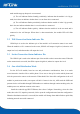

Table Of Contents
- 1.Product Profile
- 2.Functional Description
- 2.1 WiFi Indicator Flashing Description
- 2.2 Wifi Connection Status Indicator Pin
- 2.3 Socket Connection Status Indicator Pin
- 2.4 One-click Distribution Mode
- 2.5 Web Distribution Function
- 2.6 Serial to WIFI STA
- 2.7 Serial to WIFI AP
- 2.8 Serial Port Working State Conversion
- 2.9 Serial Port-network Data Conversion
- 2.10 Application Areas
- 3. AT Instructions
- 3.1 Query Current Module Version: at+ver
- 3.2 Local Port Operation: at+CLport
- 3.3 Set up Serial Port: at+uart
- 3.4 Set up DHCP: at+dhcpc
- 3.5 Set up Wifi Connection Mode: at+netmode
- 3.6 Set up TCP Connection Mode: at+mode
- 3.7 Set up Remote IP When Modules Work as Client
- 3.8 Set up Remote Port When Module Act as Client:
- 3.9 Set Parameter Submission: at+net_commit
- 3.10 System Restart: at+reconn
- 3.11 Set the Module's ssid and Password: at+wifi_
- 3.12 Set up Socket Connection Protocol: at+remote
- 3.13 Set Network Connection Parameters: at+net_ip
- 3.14 Query Network Connection Status in STA Mode:
- 3.15 Query Module MAC Address: at+Get_MAC
- 3.16 Set the Frame Length: at + uartpacklen
- 3.17 Set the Frame Time:at+uartpacktimeout
- 3.18 Set Bluetooth Name: at+ble_name
- 3.19 Configuration Software Description
- 4.Upgrade Introduction
- 8. Appendix A Document Revision

4
2. Functional Description
2.1 WiFi Indicator Flashing Description
The module is flashed by the LED indicator in different modes, so that the module running
status can be quickly and easily known. The WiFi indicator of the module mainly has the following
status:
(1) The wifi indicator flashes twice periodically: indicates that the module is in the
one-click distribution mode.
(2) The wifi indicator flashes thirdly periodically: indicates that the module is in the sta
32
NC
NC
33
NC
NC
34
NC
NC
35
GPIO59
SOCKET connection status indication
36
GPIO58
WIFI connection status indication
37
NC
NC
38
UART_RXD0
Serial port 0 input for transparent transmission and at command
setting
39
UART_TXD0
Serial port 0 output, used for transparent transmission and at
command setting, need to be pulled low or left hanging
40
UART_RXD1
Serial port 1 input
41
NC
NC
42
SYS_RST_N
I
RST pin, module reset, active low, reset time ≥ 500ms
43
NC
NC
44
UART_TXD1
Serial port 1 output
45
NC
NC
46
VDD_5V
P
5V input
47
NC
NC
48
NC
NC
49
GPIO33
Wifi indicator
50
GND
Ground
Ground
51
NC
NC
52
NC
NC