
User's Manual
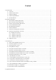


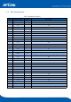


Table Of Contents
- 1.Product Profile
- 2.Functional Description
- 2.1 WiFi Indicator Flashing Description
- 2.2 Wifi Connection Status Indicator Pin
- 2.3 Socket Connection Status Indicator Pin
- 2.4 One-click Distribution Mode
- 2.5 Web Distribution Function
- 2.6 Serial to WIFI STA
- 2.7 Serial to WIFI AP
- 2.8 Serial Port Working State Conversion
- 2.9 Serial Port-network Data Conversion
- 2.10 Application Areas
- 3. AT Instructions
- 3.1 Query Current Module Version: at+ver
- 3.2 Local Port Operation: at+CLport
- 3.3 Set up Serial Port: at+uart
- 3.4 Set up DHCP: at+dhcpc
- 3.5 Set up Wifi Connection Mode: at+netmode
- 3.6 Set up TCP Connection Mode: at+mode
- 3.7 Set up Remote IP When Modules Work as Client
- 3.8 Set up Remote Port When Module Act as Client:
- 3.9 Set Parameter Submission: at+net_commit
- 3.10 System Restart: at+reconn
- 3.11 Set the Module's ssid and Password: at+wifi_
- 3.12 Set up Socket Connection Protocol: at+remote
- 3.13 Set Network Connection Parameters: at+net_ip
- 3.14 Query Network Connection Status in STA Mode:
- 3.15 Query Module MAC Address: at+Get_MAC
- 3.16 Set the Frame Length: at + uartpacklen
- 3.17 Set the Frame Time:at+uartpacktimeout
- 3.18 Set Bluetooth Name: at+ble_name
- 3.19 Configuration Software Description
- 4.Upgrade Introduction
- 8. Appendix A Document Revision

3
1.5 Pins Introduction
Table 2 Module pin interface
Pin
Network Name
Type
Description
1
NC
NC
2
NC
NC
3
NC
NC
4
NC
NC
5
NC
NC
6
NC
NC
7
NC
NC
8
GND
Ground
GND
9
NC
NC
10
3V3
P
External power supply pin: 3.3V@ 200mA
11
NC
NC
12
NC
NC
13
NC
NC
14
NC
NC
15
NC
NC
16
GPIO0
I/O
ES0 pin, pull down 1 second, serial 0 into AT command mode;
Pull down ≥ 8 seconds, restore factory default parameter settings
17
NC
NC
18
NC
NC
19
NC
NC
20
NC
NC
21
NC
NC
22
NC
NC
23
NC
NC
24
NC
NC
25
NC
NC
26
NC
NC
27
NC
NC
28
NC
NC
29
NC
NC
30
NC
NC
31
NC
NC