
User's Manual

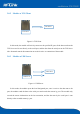
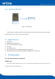
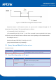
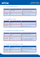

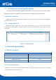
Table Of Contents
- 1.Product Profile
- 2.Functional Description
- 2.1 WiFi Indicator Flashing Description
- 2.2 Wifi Connection Status Indicator Pin
- 2.3 Socket Connection Status Indicator Pin
- 2.4 One-click Distribution Mode
- 2.5 Web Distribution Function
- 2.6 Serial to WIFI STA
- 2.7 Serial to WIFI AP
- 2.8 Serial Port Working State Conversion
- 2.9 Serial Port-network Data Conversion
- 2.10 Application Areas
- 3. AT Instructions
- 3.1 Query Current Module Version: at+ver
- 3.2 Local Port Operation: at+CLport
- 3.3 Set up Serial Port: at+uart
- 3.4 Set up DHCP: at+dhcpc
- 3.5 Set up Wifi Connection Mode: at+netmode
- 3.6 Set up TCP Connection Mode: at+mode
- 3.7 Set up Remote IP When Modules Work as Client
- 3.8 Set up Remote Port When Module Act as Client:
- 3.9 Set Parameter Submission: at+net_commit
- 3.10 System Restart: at+reconn
- 3.11 Set the Module's ssid and Password: at+wifi_
- 3.12 Set up Socket Connection Protocol: at+remote
- 3.13 Set Network Connection Parameters: at+net_ip
- 3.14 Query Network Connection Status in STA Mode:
- 3.15 Query Module MAC Address: at+Get_MAC
- 3.16 Set the Frame Length: at + uartpacklen
- 3.17 Set the Frame Time:at+uartpacktimeout
- 3.18 Set Bluetooth Name: at+ble_name
- 3.19 Configuration Software Description
- 4.Upgrade Introduction
- 8. Appendix A Document Revision

18
4
.2 Introduction of Network Upgrade Methods
In order to realize the network upgrade of the module, it is necessary to connect the line module
through wifi, and then to upgrade the data transmission according to the ip of the module.
4.2.1 Router Connection
Modules that need to be upgraded can be configured and connected to routers through serial port configuration
tools, or ap mode can be used.
4.2.2 Lookup Module IP
Because you need to input the ip, of the module when upgrading, you can go to the router to find the
corresponding ip, of
the module or use HLK-_Discover to search the corresponding ip. for the module in the local
area network.
Figure 18. Lookup module ip
5.
Electrical Specification
5.1 Electric Parameter
Electric parameter(for information only)
Power input voltage DC:5±0.2V
No-load running current 60±20mA @5V
Module average power consumption about 300mW
Module current peak 450mA
Requirements for power supply current ≥800mA
5.2 Current Waveform
Module test environment:single module without baseboard test, single and dual frequency antenna. The module
current peak shall refer to the table above.