User Manual
Table Of Contents

Chapter 5 DataReader Installation and Operating Instructions
- 60 - Hi-G-Tek Ltd. Micro electro nic s & A sset Tra cking Techno logy
than those certified with the product is expressly forbidden in accordance
with FCC rules CFR47 part 15.204.
5.8 DataReader Operation Instructions
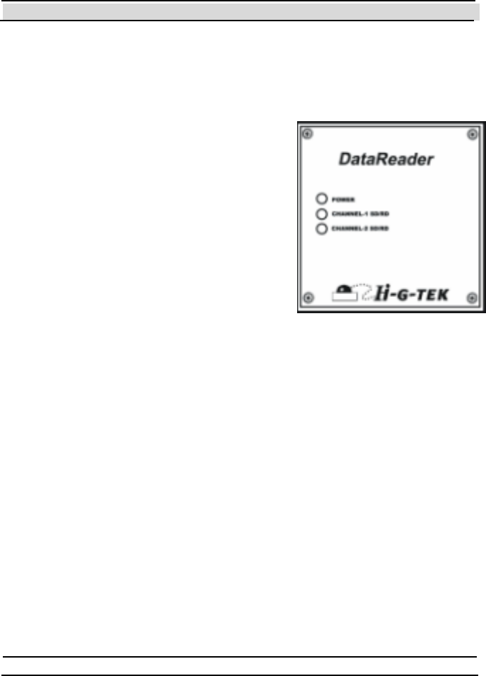
Three LED indicators are located on the left-
hand side of the electronics compartment.
5.8.1 Power Indicators:
The DataReader is activated by connecting it
t o a power supply. At power ON and self-
test the power indicator's color alternates
between green and red for several seconds.
If the check result is OK, the indicator
remains green. If a problem was det ect ed, the indicator remains red.
This LED also has a special meaning when performing firmware download:
On MCU firmware download, the indicator alternates between green
and red.
On RF Modem firmware download - the indicator remains off.
5.8.2 Channel 1 SD/RD Indicator:
When t his indicator is red, t he unit is in SD (sending RF dat a) mode.
When the indicator is green, the unit is in RD (receiving RF data)
mode.
When the indicator is off, it is in stand-by mode.


