User Manual
Table Of Contents

Chapter 5 DataReader Installation and Operating Instructions
Hi-G-Tek Ltd. Micro electronics & Asset Tracking Technology - 51 -
5.2.5 RS-485 Half Duplex Wiring Diagram
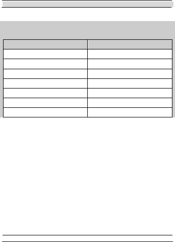
Pin assignment for PWR/COM IN ( P1) & PWR/ COM OUT ( P3)
Funct ion Pin Number
Positive Power 1
Positive Power 2
Signal GND 3
Negative Power 4
Negative Power 5
TX/RX-A 6
TX/RX-B 7
5.3 Chaining DataReaders Together
Up to 32 DataReaders can be connected in a daisy chain using RS-485. The
last DataReader in the chain should be terminated by a 120 Ohm resistor
between the RXA and the RXB.
For the Outdoor version, the user can decide to create either an internal or
external termination switch. The internal termination switch is created by
setting to ON the termination switch (S2) of the last DataReader in the
daisy chain.
An external termination is relevant for the Indoor version only. An RS-485
to RS-232 adapter termination should be provided for the adapter receive
channel.


