
Operating Instructions
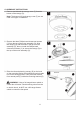

WIRING
WARNING:
with this fan are designed to accept only one 12-gauge house wire and two lead wires from the fan. If
your house wire is larger than 12 gauges and/or there is more than one house wire to connect to the
fan lead wire (red), consult an electrician for the proper size wire connectors to use.
CAUTION: Be sure the outlet box is properly grounded or that a ground (green or bare) wire is present.
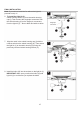
diagram and these steps:
Push-in Wire
Important: The wire harness and the Bare/Green
(ground) supply wire will be connected later. If supply Receiver
wires are different colors than referred to above, a
professional electrician should determine proper wiring.
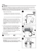
CAUTION: Fan must be installed with included
receiver. Antenna Wire Harness
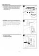
the mounting bracket (E) to the Bare/Green (ground)
supply wire using a wire connector (BB). Note:
Closemount installation does not use a downrod (A),
E
Then, wrap electrical tape (not included) around the
wire connector (BB) down to the wire.
Hardware Used
BB Wire Connector x 1
A
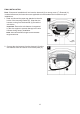
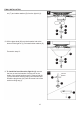
3.
Turn the spliced/taped wires upward and gently push
the wires and connectors into the outlet box.
WARNING: Ensure no bare wire strands are visible
after making connections. Place White wire connections
on opposite sides of outlet box from the Black.
3
12
n
preassembled to the White wire from the receiver of
/
e
White (Common/Neutral)
r
a
G
Connector
wire hole in push-in wire connector preassembled to
e
1. Make the following wire connections according to the
i
1
n
e
the empty wire hole of the push-in wire connector )
r d
h
e
W
2. Connect the Green wires from the downrod (A) and
so there will only be two Green wires to connect.
BB