OWNERS MANUAL HF Oil Content Monitor (OCM) HF scientific inc. 3170 Metro Parkway Ft. Myers, Fl 33916 Phone (239) 337-2116 Fax (239) 332-7643 Email: info@hfscientific.com Catalog No. 22543 (1/03) Rev. 3.
Declaration of Conformity Application of Council Directive Standard to which Conformity is Declared: Product Safety – Tested and Passed CE EN61010-1: 1990 + A1: 1992 (73/32 EEC) Immunity and Emissions – Tested and Passed EN61326: 1998, Class A Manufacturer’s Name: HF scientific, inc.
Table of Contents Declaration of Conformity ........................................................................................................... i Specifications................................................................................................................................ 1 1.0 Using this Instruction Manual ......................................................................................... 2 2.0 Unpacking the Instrument........................................................
8.2 9.0 System Failure Error................................................................................................. 15 Routine Maintenance ..................................................................................................... 16 9.1 Cleaning the Optical Chamber (Sample Tube) ....................................................... 16 9.2 Replacing the Desiccant Cartridge ........................................................................... 16 9.
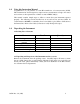
Specifications Measurement Range 0-30 PPM, Trending 30-50 PPM Accuracy Less than ±5 PPM Resolution 1 PPM Response Time Less than 20 seconds Power Requirements 90-250 VAC, 47-90Hz, 6 VA Display Liquid Crystal Display Two User Settable Alarms 120-240VAC 2A Form C Relay with suppressors, or 120-240VAC 1A Form A Zero –crossing Solid State Relay Analog Output Signals 4 - 20 mA Water Pressure 0.1 - 8 bar (1-116 psi.) Flow Rate 1 Liter/min. regulated (.
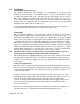
1.0 Using this Instruction Manual Congratulations on your purchase of a new HF scientific inc. oil content monitor (OCM). This instrument has been designed for simple and easy measurement of bilge oil in water and conforms to the requirements of I.M.O. resolution MEPC. 60(33). This manual contains simple steps to follow to ensure that your instrument operates properly. The following sections describe how to use and care for your new OCM.
3.0 Installation 3.1 Mounting and Site Selection The OCM is designed for wall mounting. If wall mounting is not practical, the instrument can be mounted on any suitable surface. Choose a location that is easily accessible for operation and service and ensure that the front display rests at eye level. The overall mounting dimensions of the instrument are shown in Figure 1. For ease of service there should be about 45cm (18”) free area above the OCM.
3.3.1 Power Source The power source required is 90 – 250VAC, 47-90Hz. The power consumption is 6VA. Connections are made at the far right hand terminals. Please observe safe wiring practices. It is recommended that a circuit breaker or switch be placed prior to the power connection to the OCM to allow for service. Note: Only qualified electricians should be allowed to perform the installation of the instrument as it involves a line voltage that could endanger life. 3.3.
4.0 Becoming Familiar with the Instrument The user interface of the OCM has been designed with a 4 key Touch Pad and a digital user display with two rows of display information. 4.1 The Touch Pad The MODE key is used to cycle between the four modes of the OCM: AUTO (measurement) mode, CAL 0 ADJ (Zero Adjust Calibration) mode, SETUP (Instrument Configuration) mode, and CAL (Calibration) mode. The ↵ key enters the option (or mode) that is highlighted or chosen.
5.0 Routine Operation The OCM is designed to measure and display the concentration of oil (in PPM by weight) in the bilge water according to I.M.O. resolution MEPC. 60(33). Readings above 50 PPM are outside of the range of this instrument. 5.
6.0 Instrument Configuration (SETUP mode) The OCM provides you the ability to customize your instrument according to your needs at any time during normal operation. This section describes how you can customize your instrument. NOTE: To skip the selection of the SETUP mode, simply press the MODE key. 6.1 Configuring the Alarms Enter the SETUP mode of the OCM by pressing the MODE key until SETUP is illuminated. The level at which the alarm(s) will activate is called the set point.
The current selected number of seconds will be shown. You can select the desired number of seconds for the “delay on” time for this alarm using the t and u buttons. Once you have set the desired delay time, press the ↵ button to accept it. Delay Off: Next, the following display will appear to allow you to select the number of seconds currently set for the “delay off” time. The current selected number of seconds will be shown.
The current selected number of seconds will be shown. You can select the desired delay on time for this alarm using the t and u buttons. Once you have set the desired delay time, press the ↵ button to accept it. Note: A system alarm will activate when an internal system failure occurs. Please note that the user settable relays are failsafe in that they will activate if an internal system failure or power loss occurs. 6.
The three access codes used in the instrument: code 333 will provide access to instrument calibration, code 444 will provide access to instrument configuration, and 222 will provide access to the zero adjust calibration. See section 5.2 for more information on this security feature. The security key will be highlighted on this display at this time and the lower row of the display will indicate the operational status of the security access option (on or off).
7.0 Calibration Procedures The OCM has been factory-calibrated at HF scientific, inc.. It is possible to use the instrument directly out of the box. However, re-calibration of the instrument using oilfree water and the supplied 15 PPM calibration standard is recommended to allow the user to become familiar with the operation of the instrument and the calibration procedures 7.
the lower row of the LCD display. 15. This is the final step for calibration at the 0 PPM level; if you wish to skip this step without calibrating the 0 PPM, simply press the ↵ button. However, if you are satisfied and wish to complete calibration on the 0 PPM level use the tu arrows to select the word YES on the lower row of the display and then press the ↵ button to initiate calibration. 16. Both the CAL and STORE blocks will flash during the operation.
5. Replace the cleanout plug. 6. Press the ↵ key to initiate the calibration on 15 PPM water. The word CAL will appear on the upper row of the LCD display and the word NO will appear on the lower row of the LCD display. 7. This is the final step for calibration at the 15 PPM level; if you wish to exit without calibrating simply press the ↵ button.
below) Press the ↵ key to initiate the zero adjust calibration on your oil-free sample. The word CAL will appear on the upper row of the LCD display and the word NO will appear on the lower row of the LCD display. This is the final step for calibration for the zero adjust; if you wish to exit without calibrating simply press the ↵ button.
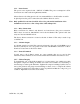
8.0 Self-Diagnostics: System Troubleshooting 8.1 System Warning Message(s) Automatic warning messages are generated by the OCM to provide you with specific diagnostic information about the instrument. These are only messages and they do not indicate failure of any component in the instrument. The following table lists the warning messages and their associated meanings: WARNING ASSOCIATED MEANING TYPICAL CAUSE W01 Lamp Failure Lamp has too low an output.
9.0 Routine Maintenance 9.1 Cleaning the Optical Chamber (Sample Tube) Proper measurement of the oil content of sample water requires that the sample tube be free of debris. Cleaning the sample tube is accomplished by first purging the system: 1. Stop the flow of sample water to the OCM. 2. Run oil free water for several minutes through the instrument and then shut off the flow to the instrument (ensure that the sample tube remains full with clean water). 3.
10. Push the electronics module back in and tighten the four sensor cover screws. Please note that the OCM will require a complete calibration as described in sections 6.1.1 and 6.1.2. 10.
11.0 Warranty HF scientific, inc., as manufacturer, warrants to the original purchaser of this instrument that it will be free of defects in material and workmanship, in normal use and service, for a period of one year from date of delivery to the original purchaser. HF scientific, inc.’s, obligation under this warranty is limited to replacing, at its factory, the instrument or any part thereof.
12.0 Figures Figure 1: Mounting Dimensions for the instrument [inches (mm)] OCM Rev. 3.
Figure 2: Recommended Plumbing for the instrument. OCM Rev. 3.
Figure 3: Electrical connections for the instrument. OCM Rev. 3.
(3) (1) (5) (2) (4) Figure 4: Graphics of the LCD Display. The upper row of the display is identified as item (1). The lower row of the display is identified as item (2). Several status indicators are identified as item (3). Several other indicators are shown as item (4). Finally, the prompt for the security access code is shown as item (5). (1) (2) Figure 5: The LCD Display shown when the security code is to be entered. The prompt for the security access code is shown as item (1).
Figure 6: Location and removal of the desiccant cartridge on the instrument. OCM Rev. 3.
Figure 7: Lamp Replacement. OCM Rev. 3.
Figure 8: Menu Flow Chart OCM Rev. 3.
13.0 Approvals OCM Rev. 3.
OCM Rev. 3.
OCM Rev. 3.
OCM Rev. 3.
OCM Rev. 3.
OCM Rev. 3.