
Manual

LLL L
PUMP (-)
SOL-
RELAY (COM)
PUMP (+)
RELAY (NC)
RELAY (NO)
SOL+
RELAY (NO)
RELAY (COM)
RELAY (NC)
BLU
RED
100-240 VAC
47-63 HZ
175 VA
BLAC
RED
BLUE
BROWN
GREEN/YELLOW
TO HEATER
TERMINAL
BLOCK
E (COM)
(+)
K (-)
(+)
TO PUMP
TO DRAIN
SOLENOIDS
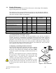
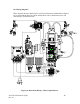
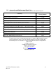
Figure 11: Power Box Wiring
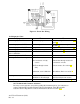
10.4 Diagnostic Chart
Symptom Cause Cure
Lower display shows MA
4-20 mA loop open Check wiring. See sections 3.3.4
and 7.2
Lower display shows DESC
Desiccant pouch bad Change desiccant pouch. See
section 9.2
Lower display shows LAMP
Lamp failed Replace lamp. Refer to section 9.3
Lower display shows CLN
Ultrasonic cleaning failure Refer to section 8.1
Lower display shows CAL Err
after a calibration.
100%T Calibration failure Refer to section 5.2
Lower display shows FAIL
Major system fault Refer to section 10.1 & 10.2
Readings are lower than expected
(1) Bubbles in solution
(2) Condensate or leaky
cuvette
(3) Flow through cuvette
dirty
Instrument out of calibration
Increase P-ST. Refer to section 7.13
Check flow through cuvette for
condensate or leaks.
Clean cuvette. See section 9.1
Recalibrate. Refer to section 5
Readings are erratic
(1) Bubbles in solution
(2) Debris in flow through
(1) See above
(2) Clean debris from cuvette
Readings are higher than expected Instrument out of calibration Recalibrate. Refer to section 5
10.5 Technical and Customer Assistance
If for any reason assistance is needed regarding this instrument please do not hesitate to
contact either the HF scientific Technical Service Department or the HF scientific
Customer Service Department. Contact information is shown on section 10.2.
AccUView Wastewater (1/09) 31
Rev. 2.9