OWNERS MANUAL HF – Triple Validation Turbidimeter 0-10, 0-100 NTU HF scientific, inc. 3170 Metro Parkway Ft. Myers, FL 33916 239-337-2116 Catalog No. 22569 (5/02) Rev. 1.7 (.
DECLARATION OF CONFORMITY Application of Council Directive Standard to which Conformity is Declared: Product Safety - Tested and passed CE EN61010-1:1990 + A1:1992 (73/32 EEC) Immunity and Emissions – Tested and passed EN61326:1998, Class A Manufacturer’s Name: HF scientific, inc.
Table of Contents Specifications.................................................................................................................................. 1 1.0 Overview................................................................................................................................. 1 1.1 Unpacking and Inspection of the Instrument and Accessories ........................................... 2 1.2 The Display..............................................................................
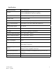
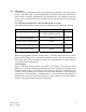
Specifications Measurement Range 0.01 –100.0 NTU Accuracy ±2% of reading plus 0.01 NTU (0-10 NTU) ±5% of reading plus 0.1 NTU (10-100 NTU) Resolution 0.0001 NTU on low readings Response Time Less than 8 seconds Display Multi-Line Liquid Crystal Display Two User Programmable Alarms 120-240VAC 2A Form C Relay with suppressors Analog Output Signals 4 - 20 mA Water Pressure 0.1 - 8 bar (1-116 psi.) Flow Rate 0.5 Liter/min. regulated (.
1.0 Overview The TVT process turbidimeter allows you to measure the turbidity of your process water on-line. The White Light TVT has been designed to meet the design criteria specified by the US EPA on turbidity measurement. The Infra-Red TVT was designed to meet the design criteria specified in ISO 7027 and DIN 27027 for the measurement of the turbidity of a sample. 1.
Figure 1 – Display used in the instrument. All items used on the display are shown in this figure 1.3 The Touch Pad Figure 2: The Instrument touch pad. Figure 2 illustrates the touch pad. The touch pad has four buttons: MODE, ↵, t, and u. The MODE button is used to cycle between the three operational modes of the instrument: CAL, SETUP, and AUTO (Measurement) mode. The ↵ button enters the option (or mode) that is highlighted or chosen.
2.0 Safety This manual contains basic instructions that you must follow during the commissioning, operation, care and maintenance of the instrument. The safety protection provided by this equipment may be impaired if it is commissioned and/or used in a manner not described in this manual. Consequently, all responsible personnel must read this manual prior to working with this instrument.
3.0 Installation and Commissioning 3.1 Mounting & Site Selection The instrument is designed for wall mounting. If wall mounting is not practical, the instrument can be mounted on any suitable level surface. For ease of service there should be about 45cm (18”) free area above the instrument; this will ensure enough room for calibration and cleaning the optical well. Choose a location that is easily accessible for operation and service and ensure that the front display rests at eye level.
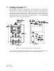
3.2 Plumbing The recommended plumbing for the instrument is shown in Figure 4. The instrument is designed to limit the flow to the range of 0.4 – 0.6 liters/minute depending on the system backpressure. Ensure that you supply the instrument with a process flow capable of sustaining this level. Quick-connect fittings are supplied on the inlet and outlet of the instrument; these fitting help speed up calibration procedures. These fittings will accept 0.25” OD x 0.170 ” ID tubing.
Note: Only qualified electricians should be allowed to perform the installation of the instrument as it involves a line voltage that could endanger life. Figure 5: Electrical Connections for the Instrument TVT2 (5/02) Rev. 1.7 (.
Power: The instrument is equipped with a 90-250 VAC, 50-60 Hz switching power supply; please verify that the line voltage falls within these specifications. If the line voltage does not fall within these specifications please consult with the HF scientific, inc. Technical Services Department to determine the proper method for powering your instrument. While making your connections, refer to Figure 5.
In certain instances, during normal operation, the instrument will display a row of dashes across the upper row of the display This indicates that either the instrument is performing an auto-ranging function, or the sample has a substantial amount of bubbles. If the dashes remain for an extended period of time please ensure that the sample does not have a large amount of bubbles present; if there are not bubbles present, please contact the HF scientific, inc.
The security code has three numbers that are selectable one at a time. Notice that the first number in the code is flashing; the flashing indicates that this is the number to be changed. Use the tor u arrows to select the value of the first number in the code and then press the ↵ button to accept the first number of the code. After you have pressed enter, the second number in the code will start to flash. Proceed as with the first number. Then repeat the process for the third number in the access code.
5.1 Calibration Standards We recommend that you use the following materials during calibration to achieve the accuracy stated in this manual: 1. De-ionized water filtered through a 0.02 µm filter 2. 10.0 NTU Formazin primary standard, or 10.0 NTU pour through Calibration Standard available from HF scientific, inc. 3. 100 NTU Formazin primary standard, or 100 NTU pour through Calibration Standard available from HF scientific, inc. It is well known that diluted Formazin is unstable.
8. Pour the 10.0 NTU calibration standard into the sample well (ensure that the well is completely filled). Place the black cleanout plug back on the sample well (to block light). Note: If you choose to use Formazin, be sure to clean the sample well immediately after using Formazin and prior to returning to the measurement mode. 9. Press the ↵ button to indicate to the instrument that you wish to calibrate on the 10.0 NTU calibration level.
When the calibration procedure for the 10.0 NTU level is complete the CAL and STORE blocks will stop flashing. You will see the following on the display: 11. Then, you will see the following on the display: 12. Drain the 10.0 NTU calibration standard from the sample well and rinse the well at least twice with 0.02 NTU water. 13. Fill the well with 0.02 NTU water and then place the black cleanout plug on the sample well (to block light). 14.
Pressing either the MODE button or the ↵ button will complete calibration. If you press the MODE button two times you will return to the AUTO mode. Note: 1. At any point in time during calibration you can cycle through the required calibration points (0.02 NTU, 10 NTU, and 100 NTU) by pressing either the t or u buttons. This allows you to individually calibrate with a particular calibration standard. 2.
5. At this point, the lower row of the display will indicate the operational status of the offset function (on or off). You may change this status by using the t and u buttons. Once you have set the desired operational status of the offset function press the ↵ button to accept it. If you turned the option off, you will return to the SETUP mode. Press MODE to return to the automatic measurement mode. 6.
7.0 Instrument Configuration (Range) In order to reduce maintenance during calibration, all TVT’s are shipped from the factory with a range of 0-10 NTU. The instrument is capable of, and has been factory calibrated for a range of 0-100 NTU. It is recommended that this higher range not be used unless needed. 7.1 0-100 NTU Range Selection To select this range, loosen the four front panel screws and pull the front chassis forward about 10 cm (4 inches).
Change the resolution by pressing the t or u button. When you have selected the desired digit resolution press the ↵ button. After pressing the ↵ button, the YEAR block will be highlighted and the current year will be displayed 8.2 Setting the Year With the YEAR block highlighted and the year displayed, change the displayed year using the t or u buttons. When you have selected the proper year press the enter button (↵) to accept the year. 8.
Select the correct day by pressing the t or u buttons to change the displayed day. When you have selected the proper day, press the ↵ button. 8.4 Setting the Time After pressing the ↵ button, the TIME block will be displayed and you will see the time displayed on the upper LCD screen in 24-hour format. The number flashing corresponds to the hour. Select the correct hour by pressing the t or u button to change the displayed hour. When you have selected the proper hour, press the ↵ button.
8.5 Programming the Alarms The instrument is equipped with two relays that are designed to operate as two independent programmable alarms. You must input three types of information to fully program each alarm: 1. The alarm function (HI, LOW, or OFF) 2. The alarm set point (level at which the alarm activates) 3. The delay time for the alarm: the time that the set point must be exceeded prior to alarm activation (prevents ringing in the relay) These three items are described below.
If you selected to turn the alarm OFF, you will be immediately prompted to set up alarm 2 (go to section 8.5.2). If, on the other hand, you selected one of the other functionalities you will be prompted to set the delay times. Alarm 1 Delay Times: Delay On: The following display will appear to allow you to select the number of seconds currently set for the “delay on” time. The current selected number of seconds will be shown.
functionalities you will be prompted to set the delay times and the set point as with Alarm #1. Once you complete the selections for Alarm #2 you will be prompted to set up the analog output. 8.6 Setting the Analog Output (O/P) The output (O/P) selection allows you to turn the 4-20 mA analog output on, or off. You can select the desired analog output operation using the t and u buttons. Once you have set the desired operation, press the ↵ button to accept it.
Select the turbidity level you wish to assign to the OHV using the t and u buttons. Once you have set the desired level, press the ↵ button to accept it. At this point you will be prompted to set up the digital output (PRINT) option. 8.7 Configuring the RS 485 I/O Port (Bi-directional Optional) Automatic/Timed Printouts: After pressing the ↵ button, the PRINT block will be highlighted. The lower row of the display will indicate whether this option is turned off or to one of the printing intervals.
Select the correct baud rate (1200, 2400, 4800, or 9600) for operation of the I/O port by pressing either the t or u button to change the displayed baud rate. When you have selected the proper baud rate press the ↵ button to continue on to configure the security access option. The other parameters for the digital communication are no parity and one (1) stop bit. Note: The information printed out in the timed printout has the format: x.xx NTU dd Mmm yyyy hh:mm.
The 5 BYTE message sent by the master computer is detailed as follows: BYTE #1 is an attention character (3A in hex format) BYTE #2 is the native address of the master instrument that is requesting information from the sensors in the RS485 loop. This address is 00 hex by definition (sent in hex format). BYTE #3 is the address of the sensor being queried (sent in hex format) BYTE #4 is the command/request to be serviced.
display at this time and the lower row of the display will indicate the operational status of the security access option (on or off). You can change the operational status of this option using the t and u buttons. Once you have set the desired security code functionality, press the ↵ button to accept it. You will now see a screen with the word END on the lower row of the display. Pressing the ↵ button will return you back to the normal automatic mode of the instrument.
9.0 Troubleshooting/System Alarm Relay 9.1 System Warning Message(s) The instrument routinely performs self-diagnostics and will automatically generate warning messages to provide you with specific diagnostic information about the instrument. These are only messages and they do not indicate failure of any component in the instrument. Normally, the cause of a warning message is external of the instrument.
When this message is indicated, contact the HF scientific, inc. Technical Services department to determine a resolution to the problem. The instrument indicates an error message “SFE” if there is a general electronics failure. Normally, this condition indicates that the instrument will require servicing; contact either the HF scientific, inc. Technical Service Department or the HF scientific, inc. Customer Service Department.
Figure 6: Removal of the Desiccant Cartridge TVT2 (5/02) Rev. 1.7 (.
11.0 Accessories and Replacement Parts List The items shown below are recommended accessories and replacement parts. Accessory HF Sure Cal check standard, Reuseable Catalog Number White Light Infrared 19780 19780 Calibration Kit, 0.02 and 10 NTU Standards, 1 Liter each 19781 19782 Calibration Kit for extended range calibration. Includes 10 and 100 NTU Standards, 1 Liter each.
12.0 Warranty HF scientific, inc., as vendor, warrants to the original purchaser of this instrument that it will be free of defects in material and workmanship, in normal use and service, for a period of one year from date of delivery to the original purchaser. HF scientific, inc.’s, obligation under this warranty is limited to replacing, at its factory, the instrument or any part thereof.