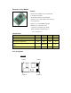
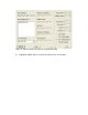
Ethernet to Serial Module Feature - Engineered for bridging serial communication to the Ethernet network - Specifically designed for interfacing with microprocessor as web enabled electronic device via serial interface - I/O pins are TTL and CMOS compatible - Miniature size of 42 x 88 x 9 mm - Low power consumption (Typ: 15mA) - Wide operating temperature range of -10 to +70 degree C Specification Operating Voltage Current Consumption Operating Temperature Data Input / Output Voltage Level (TTL) Data Rate
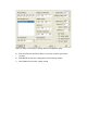
J1 pins description Pin 1 Gnd Ground connection Pin 2 Rx- Ethernet Rx- connection Pin 3 Rx+ Ethernet Rx- connection Pin 4 Gnd Ground Connection Pin 5 Tx- Ethernet Tx- connection Pin 6 Tx+ Ethernet Tx+ connection Pin 7 Gnd Ground connection Pin 8 Act Activate indicator LED connection (see scheamtic) Pin 9 Link Link indicator LED Connection (see scheamtic) Pin 10 NC No connection Pin 11 Status Status indicator LED connection (see scheamtic) Pin 12 Vcc 5V connection J2 pins
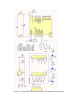
Figure 1 - Interfacing Ethernet to serial module with a PC serial port
Figure 2 - Interfacing Ethernet to serial module with Microchip microprocessor
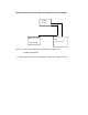
One time configuration procedure for the Ethernet to serial module 10/100 Router Ethernet module Unknown IP PC 192.168.2.188 Figure 3 - Connection needed for assigning the IP address for the Ethernet module 1) Connect the Ethernet to serial module to a PC via a switch or router.
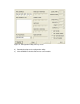
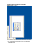
Figure 4 - Configuration utility start-up screen 2) Download and open the configuration utility. 3) Click SEARCH to find the Ethernet to serial module.
Figure 5 - Ethernet device found by the configuration utility 4) Highlight the MAC address found for the Ethernet to serial module.
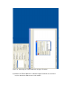
Figure 6 - Store and Verify the settings with the configuration utility 5) Enter the Ethernet module IP address and set the various parameters required. 6) Click WRITE to store the configuration to the Ethernet module. 7) Click READ and verify the settings stored.
Verify the functionality of the Ethernet to serial module (Refer to schematic on Figure 1) Figure 7 - Setting up Hyper Terminal for testing the Ethernet to serial module 8) Open the Hyper Terminal program and enter a title for the Ethernet to serial module terminal.
Figure 8 - Choosing the TCP/IP Winsock in Hyper Terminal 9) Choose the TCP/IP Winsock so that the Hyper Terminal can send and receive data to the Ethernet to serial module.
Figure 9 - Setting the correct IP address and port for the TCP/IP Winsock 10) Enter the IP address of the Ethernet to serial module.
Figure 10 - Setting the correct speed for the serial port in a new Hyper Terminal Window 11) Open a new Hyper Terminal and set the correct serial port parameters.
Figure 11 - Two Hyper Terminals showing successful connection 12) The Serial Port Terminal should display the character typed on the Ethernet module testing terminal, vice versa.