
Owner's manual


pin
MDI signal
MDI-X signal
1
TX+
RX+
2
TX-
RX-
3
RX+
TX+
6
RX-
TX-
4, 5, 7, 8
—
—
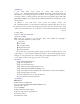
DC-IN: 5VDC power supply input
10/100M Ethernet: 10/100Base-T(X) Ethernet input and output
ACT LED indicator: Bright all along when connect power supply
LINK LED indicator: Bright all along when connected
RX/TX LED indicator: Bright all along when connect to the network, Flash
when data transfer
1, 2, 3, 4: RS-232 port (HXSP-1004A), RS-485/422 port (HXSP-1004B)
10/100Base-T Ethernet port
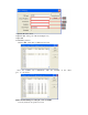
The 10/100BaseT(X) ports located on facility front panel. The PIN define of RJ45 port display as
follows, Connect by UTP or STP. The connect distance is no more than 100m. 100Mbps is used
100
Ω
of UTP 5, 10Mbps is used 100
Ω
of UTP 3, 4, 5.
RJ 45 port support automatic MDI/MDI-X operation. Can connect the PC, Server, Converter and
HUB by straight–though cable. Pin 1,2,3,6 Communication connect in MDI. 1→3, 2→6, 3→1,
6→2 are used as cross-over cable in the MDI-X port of
Converter and HUB.
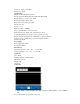
10Base-T/100Base-TX are used in MDI/MDI-X, the PIN define in the table as below.
1 8
Note: “TX±” transmit data±, “RX±” receive data±, “—”not use.
MDI (straight-through cable):
RJ45
8
1
TX+
3
TX-
6
RX+
1
RX-
2
3 RX+
6 RX-
1 TX+
2 TX-
MDI-X (cross-over cable):
RJ45
8
1
(RX+)
TX+
3
(RX-) TX-
6
(TX+)
RX+
1
(TX-)
RX-
2
1 RX+ (TX+)
2 RX-
(TX-)
3 TX+ (RX+)
6 TX- (RX-)
RS-232/485/422 interface