
Maintenance and Service Guide

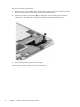
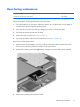

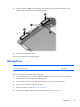
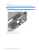
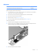
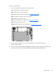
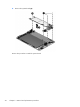
Table Of Contents

Remove the system board:
1. Disconnect the following cables from the system board:
(1) TouchScreen ZIF connector and cable
(2) Controller ZIF connector and cable
(3) Speaker cables (must be unsoldered, see
Speakers on page 18)
(4) Power/button board ZIF connector and cable
(5) Front-facing webcamera cable
(6) Antenna cable (must be unsoldered, see
Antenna on page 21)
(7) Rear-facing webcamera cable
(8) Microphone cable (must be unsoldered, see
Microphone on page 19)
2. Remove the three Phillips PM1.5×2.5 screws (1) that secure the system board to the
display panel assembly.
3. Detach the left side of the system board (2) from the display panel assembly. (The left side of the
system board is attached to the display panel assembly with double-sided adhesive.)
System board
23