INDOOR / OUTDOOR UNDERCOUNTER REFRIGERATION Ice Machine Installation and Instruction Manual
TABLE OF CONTENTS 2 3 3 4 4 6 7 8 12 14 20 20 21 21 EN SAFETY DEFINITIONS MODEL NUMBERS RATING LABEL REGULATORY/CODE REQUIREMENTS IMPORTANT SAFETY INFORMATION CONSTRUCTION DIMENSIONS INSTALLATION INSTRUCTIONS OPERATING INSTRUCTIONS MAINTENANCE PREPARING THE ICE MACHINE FOR PERIODS OF NON-USE DISPOSAL PARTS / SERVICE LIMITED WARRANTY READ THESE INSTRUCTIONS CAREFULLY AND COMPLETELY BEFORE INSTALLING OR USING YOUR APPLIANCE TO REDUCE THE RISK OF FIRE, SHOCK HAZARD, OR OTHER INJURY.
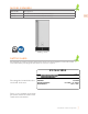
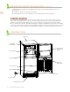
MODEL NUMBERS Model No. Description GIMR15 INDOOR / OUTDOOR ICE MACHINE, RIGHT HINGE, 15” GIML15 INDOOR / OUTDOOR ICE MACHINE, LEFT HINGE, 15” EN GIML15 shown RATING LABEL The rating label contains important information about your Hestan appliance such as the model and serial number, and refrigerant information if service is required. ICE MACHINE Model: Serial: The rating label is attached to the inside wall of the unit.
REGULATORY / CODE REQUIREMENTS Installation of this appliance must be made in accordance with local codes. In the absence of local codes, this unit should be installed in accordance with the National Electrical Code and local codes. EN This appliance must be electrically grounded in accordance with local codes or in the absence of local codes with the National Electrical Code ANSI/NFPA 70, or Canadian Electrical code CSA C22.1.
IMPORTANT SAFETY INFORMATION (continued) • • Do not make any alterations to the ice machine. Alterations could result in electric shock, injury, fire, or damage to the ice machine. The GREEN ground wire in the factory-installed power cord is connected to a screw on the rear panel where the power cord enters the ice machine. If it becomes necessary to remove or replace the power cord, be sure to connect the power cord’s ground wire to this screw upon reattachment.
IMPORTANT SAFETY INFORMATION (continued) • • • EN Keep ventilation openings, in the appliance enclosure or in the built-in structure, clear of obstructions. Do not place objects on top of the ice machine. The storage bin is for ice use only. Do not store anything else in the storage bin. PLUMBING / DRAINAGE The ice machine must be at floor level on a finished floor even if under a cabinet. The operation of the unit continually makes ice which generates a small amount of excess water which must be drained.
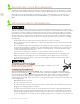
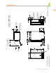
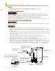
*- Leg levelers can add 1/2” [13] to these dimensions when fully extended. DOOR PANEL 7 14 8 " 3 34" CONTROL SWITCH (BEHIND DOOR) 3 29 4 " 11 33 16 " 9 2 16 " 5 3 16 " 5 21 16 " 20" 9 22 16 " 3 *10 4 " 1 38" 3 28" AIR (OUT) DIMENSIONS IN [ ] ARE mm 9 *9 16 " DRAIN OUTLET (1/2” NPT-F) WATER INLET (1/2” NPT-F) 1 3 16 " CUTOUT DIMENSIONS: 34" H - 15" W - 24" D POWER CORD 6.5 FT. [2 m] LONG 1 74" AIR (OUT) AIR (IN) MIN.
INSTALLATION INSTRUCTIONS This ice machine must be installed in accordance with applicable national, state, and local codes and regulations. EN CHOKING HAZARD : Ensure all components, fasteners, and thumbscrews are securely in place after installation. Make sure that none have fallen into the storage bin. CHECKS BEFORE INSTALLATION • Visually inspect the exterior of the shipping container and immediately report any damage to the carrier.
INSTALLATION INSTRUCTIONS (continued) 1. Make sure the space opening is correctly sized for the unit. See typical appliance dimensions on page 7 and the chart below for finished rough opening requirements: HEIGHT 34” [86.4 cm] min. 34-1/2” [87.6 cm] max. EN WIDTH DEPTH 15” [38.1 cm] 24” [61 cm] 2.
INSTALLATION INSTRUCTIONS (continued) SETUP 1. Position the ice machine in the selected permanent location. 2. Level the ice machine from side-to-side and front-to-rear by adjusting the feet. EN ELECTRICAL CONNECTION BE SURE YOU HAVE READ “IMPORTANT SAFETY INFORMATION” ON PAGE 4-5 OF THIS MANUAL TO REDUCE THE RISK OF DEATH, ELECTRIC SHOCK, SERIOUS INJURY, OR FIRE. Usually an electrical permit and services of a licensed electrician are required.
INSTALLATION INSTRUCTIONS (continued) • • • External filters, strainers, or softeners may be required depending on water quality. Contact your local Hestan Certified Service Representative for recommendations. Water supply inlet is 1/2” female pipe thread (NPT-F). A water supply line shut-off valve and drain valve must be installed (see Fig. 30 on previous page). A minimum of 1/4” nominal ID copper water tubing or equivalent is required for the water supply line.
OPERATING INSTRUCTIONS IMPORTANT NOTES ABOUT USAGE EN • • • • • • • • • • • • • • • • • • • • • 12 Only qualified service technicians should install and service the ice machine. Failure to install, operate, and maintain the ice machine in accordance with this manual will adversely affect safety, performance, component life, and warranty coverage. To reduce the risk of electric shock, make sure the control switch is in the “OFF” position before plugging in or unplugging the ice machine.
OPERATING INSTRUCTIONS (continued) STARTUP EN All parts are factory-adjusted. Improper adjustments may adversely affect safety, performance, component life, and warranty coverage. • • If the ice machine is turned off, wait for at least 3 minutes before restarting the ice machine to prevent damage to the compressor. At startup, confirm that all internal and external connections are free of leaks. 1. Open the water supply shut-off valve. 2. Make sure the control switch is in the “OFF” position.
MAINTENANCE This ice machine must be maintained in accordance with the instruction manual and labels provided with the ice machine. Consult with your local Hestan Certified Service Representative about maintenance service. EN • • • • • • Only qualified service technicians should service this ice machine. Failure to install, operate, and maintain the ice machine in accordance with this manual will adversely affect safety, performance, component life, and warranty coverage.
MAINTENANCE (continued) CLEANING SOLUTION Dilute 5 fl. oz. [148 ml or 10 tbs] of “Scale Away” with 1 gallon [3.8 l] of warm water. This is a minimum amount. Make more solution if necessary. IMPORTANT! For safety and maximum effectiveness, use the solution immediately after dilution. EN CLEANING PROCEDURE 1. Remove all ice from the evaporator and the storage bin.
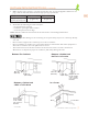
MAINTENANCE (continued) SANITIZING PROCEDURE 1. Make sure the control switch is in the “OFF” position and the storage bin is empty. 2. Remove the slope from the storage bin by carefully bending it in the center and releasing it from the 2 slope shafts. See Fig. 36. 3. Remove each separator by lifting it to the horizontal position and pushing it hard inward. See Fig. 37. EN Slope Separator Slope Shafts Fig. 37 Fig. 36 4. Disconnect the suction tube. Allow the water tank to drain. 5.
MAINTENANCE (continued) 9. Soak all of the removed parts and the scoop in the sanitizing solution for 10 minutes. If the spray assembly nozzles are clogged, clean them with a wire or a suitable brush. 10. Rinse the parts thoroughly with clean water. 11. Refit the 2 caps in their correct positions. Make sure the reducing pipe is in place in the center. See Fig. 42. 12. Slide in the spray assembly along the rails on the left and right brackets. See Fig. 43.
MAINTENANCE (continued) 18. 19. 20. 21. EN 22. 23. 24. 25. 26. 27. 28. 29. 30. Discard the sanitizing solution. Mix a new batch of the sanitizing solution and slowly pour it into the water tank. Move the control switch to the “WASH” position. After circulating the sanitizing solution for 15 minutes, move the control switch to the “OFF” position. Disconnect the suction tube. Allow the water tank to drain, then reconnect the suction tube. Repeat steps 19 through 22 one time.
MAINTENANCE (continued) CONDENSER Check the condenser once a year, and clean if required by following the steps below. More frequent cleaning may be required depending on location. • • EN Move the control switch to the “OFF” position and unplug the ice machine from the electrical outlet before cleaning the condenser. WARNING! To reduce the risk of electric shock, do not touch the control switch with damp hands. Condenser fins are sharp. Use care when cleaning. 1.
MAINTENANCE (continued) 8. Remove the discharge hose restriction and allow the water to be pumped out normally. Power to the ice machine will be restored when the water in the drain pump returns to a normal level. 9. If the ice machine fails to turn off with the discharge hose restricted or the pump fails to pump out the water, the appliance must be serviced by a qualified service technician. EN Discharge Hose Fig.
PARTS LIST Please visit the Hestan website to access parts information for your Hestan product. Use only genuine Hestan replacement parts and accessories. Genuine Hestan parts and accessories are designed to work correctly with Hestan products and offer superior service life. The use of nonHestan parts can damage the unit and may void the warranty. EN SERVICE All warranty and non-warranty repairs should be performed by qualified service personnel.
LIMITED WARRANTY (continued) To obtain the warranty coverage described in this Warranty, Hestan or its authorized distributor or dealer must receive written notice of the warranty claim within the applicable warranty period. To receive parts and/or service and the name and telephone number of the nearest Hestan authorized service representative, please contact your Hestan dealer or distributor, or Hestan’s Customer Service Department by calling 888-905-7463, or e-mailing outdoorwarranty@hestan.com.
NOTES
TABLES DES MATIERES 2 3 3 4 4 6 7 8 12 14 21 21 22 22 FR DÉFINITIONS DE SÉCURITÉ NUMÉROS DE MODÈLE PLAQUE SIGNALÉTIQUE RESPECT DE LA RÉGLEMENTATION ET DES CODES EN VIGUEUR INFORMATIONS DE SÉCURITÉ IMPORTANTES CONSTRUCTION DIMENSIONS INSTRUCTIONS D’INSTALLATION MODE D’EMPLOI ENTRETIEN PRÉPARER POUR LES PÉRIODES DE NON-UTILISATION ÉLIMINATION PIÈCES / SERVICE GARANTIE LIMITÉE LISEZ ATTENTIVEMENT ET COMPLÈTEMENT CES INSTRUCTIONS AVANT D’INSTALLER OU D’UTILISER VOTRE APPAREIL AFIN DE RÉDUIRE LES RISQUES D’IN
NUMÉROS DE MODÈLE No. Modèle Description GIMR15 MACHINE À GLACE INTÉRIEURE / EXTÉRIEURE, CHARNIÈRE DROITE, 15 ” GIML15 MACHINE À GLACE INTÉRIEURE / EXTÉRIEURE, CHARNIÈRE GAUCHE, 15 ” FR GIMR15 illustré PLAQUE SIGNALÉTIQUE La plaque signalétique contient des informations importantes sur votre appareil Hestan, telles que le modèle et le numéro de série, ainsi que des informations sur le réfrigérant si un entretien est nécessaire.
RESPECT DE LA RÉGLEMENTATION ET DES CODES EN VIGUEUR L’installation de cet appareil doit être effectuée conformément aux codes locaux. En l’absence de tels codes, installer cet appareil conformément au National Electrical Code et les codes locaux. Tous les composants électriques doivent mis à la terre conformément aux codes locaux ou, en l’absence de tels codes, au National Electrical Code ANSI/NFPA 70 ou au Code national de l’électricité du Canada CSA C22.1.
INFORMATIONS DE SÉCURITÉ IMPORTANTES (suite) • • • N’utilisez pas une machine à glaçons dont le cordon d’alimentation est endommagé. Le cordon d’alimentation ne doit pas être modifié, secoué, regroupé, alourdi, pincé ou emmêlé. De telles actions peuvent entraîner un choc électrique ou un incendie. Pour débrancher la machine à glaçons, assurez-vous de tirer sur la fiche, pas sur le cordon, et ne secouez pas le cordon. Ne modifiez pas la machine à glaçons.
INFORMATIONS DE SÉCURITÉ IMPORTANTES (suite) • • FR • • • • Pour assurer que le drain du bac de stockage reste clair, suivez les instructions de la page 19 «Vidange du Bac de Stockage» une fois tous les 3 mois ou aussi souvent que nécessaire en fonction des conditions. Si le drain du bac de stockage devient obstrué, de l’eau pourrait s’accumuler dans le bac et déborder, entraînant des dégâts d’eau coûteux.
* - Les niveleurs de pieds peuvent ajouter 1/2 po [13] à ces dimensions lorsqu'ils sont complètement déployés. PANNEAU DE PORTE 7 14 8 " 3 34" 9 2 16 " INTERRUPTEUR DE COMMANDE (DERRIÈRE LA PORTE) 3 29 4 " 11 33 16 " 5 3 16 " 20" 5 21 16 " 9 22 16 " SORTIE D'AIR 3 *10 4 " 1 38" 3 28" LES DIMENSIONS EN [ ] SONT mm 9 *9 16 " ÉVACUATION DE L'EAU (1/2” NPT-F) ARRIVÉE D'EAU (1/2” NPT-F) 1 3 16 " DIMENSIONS DE DÉCOUPE: 34po H - 15po W - 24po D CORDON D'ALIMENTATION 6.
INSTRUCTIONS D’INSTALLATION Cette machine à glaçons doit être installée conformément aux codes et réglementations nationaux, provinciaux et locaux applicables. RISQUE D’ÉTOUFFEMENT: Assurez-vous que tous les composants, attaches, et vis à oreilles sont bien en place après l’installation. Assurez-vous qu’aucun n’est tombé dans le bac de stockage. FR CONTRÔLES AVANT L’INSTALLATION • Inspectez visuellement l’extérieur du conteneur d’expédition et signalez immédiatement tout dommage au transporteur.
INSTRUCTIONS D’INSTALLATION (suite) Assurez-vous que le plancher sous l’unité est au même niveau que le plancher fini environnant. Protégez un plancher fini avec du contreplaqué, du carton ou tout autre matériau approprié avant de déplacer l’unité en place. Le non-respect de cette consigne peut endommager le sol. 1. Assurez-vous que l’ouverture de l’espace est correctement dimensionnée pour l’unité.
INSTRUCTIONS D’INSTALLATION (suite) • • FR N’installez pas la machine à glaçons dans un coin où la porte gênerait d’autres équipements ou où la machine à glaçons ne peut pas être retirée pour l’entretien. Les sections à persiennes à l’avant et à l’arrière de l’unité ne doivent pas être couvertes ou obstruées. Des obstructions pourraient empêcher une bonne circulation de l’air, ce qui pourrait endommager l’appareil. PRÉPARATION 1. Positionnez la machine à glaçons à l’emplacement permanent sélectionné. 2.
INSTRUCTIONS D’INSTALLATION (suite) • • • • • • • • • • • • • • Pour éviter d’endommager la machine à glaçons, ne faites pas fonctionner la machine à glaçons lorsque l’alimentation en eau est coupée ou si la pression est inférieure à 10 PSI [69 kPa]. Ne faites pas fonctionner la machine à glace avant la pression de l’eau est atteinte. Raccordez uniquement à l’alimentation en eau potable. Ne connectez pas à une source d’eau chaude.
MODE D’EMPLOI 5. La tension d’alimentation a-t-elle été vérifiée ou testée par rapport à la plaque signalétique? Est le alimentation une prise murale indépendante à 3 broches correctement mise à la terre? 6.
MODE D’EMPLOI (suite) • • • • • des conditions. Si le drain du bac de stockage devient obstrué, de l’eau pourrait s’accumuler dans le bac et déborder, entraînant des dégâts d’eau coûteux. Si l’eau s’accumule dans le bac et ne s’écoule pas, éteignez la machine à glaçons et fermez le robinet d’arrêt de la conduite d’alimentation en eau. Appelez pour le service.
MODE D’EMPLOI (suite) nettoyant neutre. Rincer abondamment après le Thermostat nettoyage. de contrôle 9. Déplacez l’interrupteur de commande sur la position de bac «ICE» pour démarrer le processus de fabrication de glace automatique. 10. Pour confirmer le fonctionnement du contrôle du bac, maintenez la glace en contact avec l’ampoule du thermostat de contrôle du bac. REMARQUE! Si la machine à glaçons ne s’arrête pas dans les 10 secondes, le thermostat de contrôle du bac doit être réglé.
ENTRETIEN (suite) CALENDRIER D’ENTRETIEN Le calendrier de maintenance ci-dessous est une ligne directrice. Un entretien plus fréquent peut être nécessaire en fonction de la qualité de l’eau, de l’environnement de la machine à glace et des réglementations locales en matière d’hygiène.
ENTRETIEN (suite) PROCÉDURE DE NETTOYAGE 1. Retirez toute la glace de l’évaporateur et du bac de stockage. Remarque: pour retirer les cubes sur l’évaporateur, placez l’interrupteur de commande en position «OFF» et puis remettez-le en position «ICE» après 3 minutes. Le cycle de récolte commence et les cubes sera retiré de l’évaporateur. 2. Mettez l’interrupteur de commande en position «OFF». 3.
ENTRETIEN (suite) PROCÉDURE D’ASSAINISSEMENT 1. Assurez-vous que l’interrupteur de commande est en position «OFF» et que le bac de stockage est vide. 2. Retirez la rampe du bac de stockage en la pliant soigneusement au centre et en la libérant des 2 arbres de rampe. Voir Fig. 36. 3. Retirez chaque séparateur en le soulevant en position horizontale et en le poussant fortement vers l’intérieur. Voir Fig. 37. Rampe Arbres de rampe FR Séparateur Fig. 37 Fig. 36 4. Débranchez le tube d’aspiration.
ENTRETIEN (suite) 9. Faire tremper toutes les pièces retirées et la pelle dans la solution désinfectante pendant 10 minutes. Si les buses de l’ensemble de pulvérisation sont bouchées, nettoyez-les avec un fil ou une brosse appropriée. 10. Rincez soigneusement les pièces à l’eau claire. 11. Remettez les 2 casquettes dans leur position correcte. Assurez-vous que le tuyau de réduction est en place au centre. Voir Fig.42. 12.
ENTRETIEN (suite) 18. 19. 20. 21. 22. 23. 24. 25. 26. 27. 28. 29. 30. Jeter la solution désinfectante. Mélangez un nouveau lot de solution désinfectante et versez-le lentement dans le réservoir d’eau. Placer l’interrupteur de commande en position «WASH». Après avoir fait circuler la solution désinfectante pendant 15 minutes, placez l’interrupteur de commande en position «OFF». Débranchez le tube d’aspiration. Laissez le réservoir d’eau se vider, puis rebranchez le tube d’aspiration.
ENTRETIEN (suite) CONDENSEUR Vérifiez le condenseur une fois par an et nettoyez-le si nécessaire en suivant les étapes ci-dessous. Un nettoyage plus fréquent peut être nécessaire selon l’emplacement. FR • • Placer l’interrupteur de commande en position «OFF» et débrancher la machine à glaçons de la prise électrique avant de nettoyer le condenseur. ATTENTION! Pour réduire le risque de choc électrique, ne touchez pas l’interrupteur de commande avec les mains humides.
ENTRETIEN (suite) 7. Versez encore 24 - 30 onces [710 - 890 ml] d’eau dans le bac de stockage de la machine à glaçons, puis restreignez complètement le tuyau de vidange pendant que la pompe de vidange fonctionne. Voir Fig. 49. Versez plus d’eau dans le bac de stockage de la machine à glaçons jusqu’à ce qu’elle s’éteigne. La pompe de vidange continuera de fonctionner. Vérifiez les fuites. 8. Retirez la restriction du tuyau de décharge et laissez l’eau s’écouler normalement.
PIÈCES Veuillez visiter le site Web Hestan pour accéder aux informations sur les pièces de votre produit Hestan. Utilisez uniquement des pièces de rechange et des accessoires d’origine Hestan. Les pièces et accessoires d’origine Hestan sont conçus pour fonctionner correctement avec les produits Hestan et offrir une durée de vie supérieure. L’utilisation de pièces autres que Hestan peut endommager l’appareil et annuler la garanti.
GARANTIE LIMITÉE (suite) garantie applicable. Pour recevoir des pièces et/ou des services d’entretien et le nom et le numéro de téléphone du représentant de service agréé par Hestan le plus proche, veuillez contacter votre distributeur ou concessionnaire Hestan ou le service clientèle de Hestan au 888-905-7463, ou en envoyant un courriel à outdoorwarranty0@hestan.com.
NOTES
NOTES
RETAIN THIS MANUAL FOR FUTURE REFERENCE CONSERVEZ CE MANUEL POUR UNE RÉFÉRENCE FUTURE Hestan Commercial Corporation 3375 E. La Palma Ave.