
Product Manual
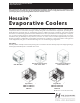
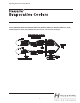

Operating Instructions & Parts Manual
R
Ducted Models: A68S/D, A48S/D,
A38S/D and RM4808S/D,
RM6808S/D, RM4812S/D,
RM6812S/D RM3808S/D
NOTE: To be installed by a licensed
professional technician.
Disconnect all
power to the
evaporative air cooler
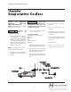
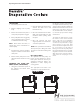
Install evaporative air cooler in a
well ventilated area. A common
equation for air ow is for every
open area of 1 x 1 feet there
should be 500 CFM of injected air.
Assure the mounting surface is
able to bear the weight of the
evaporative air cooler.
1.
2.
NOTE: The weight of the unit is
increased when water is added.
Conrm the electrical supply is
adequate for the requirements of
the unit.
3.
The evaporative
air cooler must
be installed according to all natio-
nal and local electrical codes. The
installation must be performed by
a qualied technician.
Assure that the mounting surface
is level in all directions.
4.
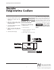
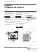
Float Valve Assembly
The following parts are included:
Float Valve
O-Ring
Nut
1/4” hose oppressor
Barrel Nut
Remove the oat valve and parts
(listed above) from inside the unit.
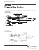
Push the plastic o-ring onto the
threaded shaft of the oat valve
until snug against the back.
Pass the shaft of the oat valve
through the pre-drilled hole in the
unit.
2.
1.
3.
Secure with the plastic nut.
Insert 1/4” water hose into the
barrel nut.
Insert the 1/4” plastic hose
oppressor.
Countersink the hose edge that
will be placed up against the oat
valve shaft.
4.
5.
6.
7.
Place the hose edge to the oat
valve shaft and tighten with the
barrel nut.
8.
Check for leaks.
9.
Adjust the water level
requirement for your unit.
10.
3