
User Manual

MCM-8 II Iss2
Preliminary User Guide v2.0
3
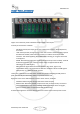
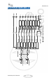
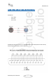
FRONT PANEL OVERVIEW
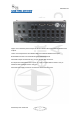
Upper row on the front panel is dedicated to the 8 mixer’s main inputs.
Controls per channel are as follows:
- ON: When pressed, the output of the slot is added to the mix bus. When depressed,
it’s muted.
- “500”: When pressed, the signal going to the mixer section is taken from the output of
the 500 series module, while when not pressed, it is taken from the input of the
enclosure. This allows bypassing the module when summing, or using the mixer with
an empty slot.
- FADER: Attenuates the signal sent to the mix bus from unity to minus infinity. Fader all
clockwise means unity gain, whilst 12 o’clock means an approximate 20 dB of
attenuation. (or -20dB of gain).
- PAN: Places the signal within the stereo spectrum, left, center, right or any
intermediate setting. The panoramic law follows a standard in which if a 0dB signal is
hard panned, it is -3dB when center panned.
Lower zone is dedicated to the 500 series modules. Any module following the API protocol
(both mechanically and electrically) will be compatible with the unit.
Right part of the unit is dedicated to the mixer’s center section, as follows:
- VU Meters: Measuring the average level at the master outputs.
- Master Fader: Attenuates the Mix’s output from unity to minus infinity. The control
has a stepped feel for easy recall of settings. Fader all clockwise means unity gain,
whilst 12 o’clock means an approximate 20dB of attenuation.
At the bottom right there are LEDs showing the correct status of the external power source.