MCM-8 II PRELIMINARY USER GUIDE v1.0 © 2018 Heritage Audio S.L. is the solely owner of the copyright of all information and drawings contained in this manual which are not to be copied or reproduced by any means or disclosed in part or whole to any third party without written permission. Heritage Audio reserves the right to alter specifications without notice. The information in this manual has been carefully checked and is believed to be accurate at the time of publication.
MCM-8 II Iss2 MCM8 II VS MCM8 In 2015, Heritage Audio set a new standard in 500 Series enclosures with the addition of the OST technology. Further, we introduced the MCM8, a true transformer-based voltage summing mixer for 500 Series modules. Hundreds of units later, we have taken all our customer´s feedback and included it in the new version, the MCM8 II.
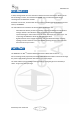
MCM-8 II Iss2 FRONT PANEL OVERVIEW Upper row on the front panel is dedicated to the 8 mixer’s main inputs. Controls per channel are as follows: - - - ON: When pressed, the output of the slot is added to the mix bus. When depressed, it’s muted. “500”: When pressed, the signal going to the mixer section is taken from the output of the 500 series module, while when not pressed, it is taken from the input of the enclosure.
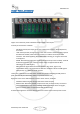
MCM-8 II Iss2 BACK PANEL OVERVIEW Upper row on the back panel corresponds to the individual XLR and combined DSUB channel outputs. Lower row corresponds to the individual XLR and combined DSUB channel inputs. Both DSUB connectors are wired following the TASCAM protocol. Stereo Mix output is located far left, on a pair of male XLR connectors. Aux Inputs are located above the 8 inputs, on a pair of female XLR connectors. They´re hardwired Left and Right and are unity gain.
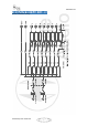
MCM-8 II Iss2 SIGNAL FLOW AND BLOCK DIAGRAM (Dsubs omitted for clarity) Preliminary User Guide v2.
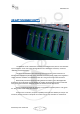
MCM-8 II Iss2 ON SLOT TECHNOLOGY ( OSTTM ) The MCM-8 II is also a 500 Series enclosure in a 4U Rack format, able to accommodate up to 8 modules. As the rest of the Heritage Audio line of 500 Series enclosures, it features “ON SLOT” Technology (OST). “ON SLOT TECHNOLOGY” takes advantage of last generation power electronics to handle power supply on a “per slot” basis. Each slot has its own power supply linear regulation stages, therefore modules are isolated from the rest.
MCM-8 II Iss2 SUMMING MIXER DESCRIPTION The MCM-8 features a passive voltage summing topology, similar to that found in the vintage Rupert Neve era discrete consoles. Passive voltage mixing requires its gain loss to be restored back to line level. Again, following the vintage topology, a stereo transformer coupled class A output amplifier is employed for this task. This amplifier is the same one used in the 1073 module.
MCM-8 II Iss2 USING THE MIXER BYPASSING FITTED MODULES As with the empty slots, using the mixer bypassing the fitted modules is nw possible using the “500” button. Preliminary User Guide v2.
MCM-8 II Iss2 BACK PANEL CONECTIONS AND PROTOCOLS All XLRs are: - Pin 1: GND Pin 2: Hot Pin 3: Cold All DSUB 25 multi pin connectors are TASCAM protocol. This same protocol is also used by AVID amongst many others, and is as follows: Preliminary User Guide v2.
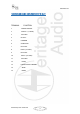
MCM-8 II Iss2 500 SERIES EDGE CONNECTOR PIN OUT TERMINAL FUNCTION 1 CHASSIS GROUND 2 OUTPUT + (+4 LEVEL) 3 NOT USED 4 OUTPUT - 5 COMMON 6 STEREO LINK 7 NOT USED 8 INPUT- (+4 LEVEL) 9 NOT USED 10 INPUT+ (+4 LEVEL) 11 NOT USED 12 +16VDC 13 POWER SUPPLY COMMON 14 -16VDC 15 +48VDC Preliminary User Guide v2.
MCM-8 II Iss2 MIXER SECTION TECHNICAL SPECIFICATIONS - Channel Input Impedance: 20 Kohm. Maximum input level: Over +27dBu Maximum output level: Greater than +26dBu into 600ohm. Frequency response: ±0.5dB 20Hz to 20kHz THD + N: Not more than 0.07% from 50Hz to 10kHz at +20dBu output (80kHz bandwidth) into 600Ω. Self-noise: -90 dBu. Heritage Audio S.L. C/ Alfonso Gomez 38, Nave 3C. 28037 Madrid Spain Tel: +00 34 917 266 189 info@heritageaudio.net Preliminary User Guide v2.0 www.heritageaudio.