
User Manual
...TRANSMITTER CONTINUED...
#
ADJUSTMENTS AND TUNING...
#
6
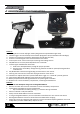
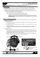
Pairing (Binding) the radio system:
The process of allowing communicaon to occur between a 2.4GHz transmier and receiver is called
“pairing” (also referred to as “matching” or “binding”). The radio system included with your product comes
pre-congured and paired from the factory. In the event your system loses this pairing, or one of the
components has been replaced, you will need to re-pair the transmier and receiver. Follow the below steps
for re-pairing your radio system
1. Ensure the transmier has good (new or charged) baeries installed and that it is powered OFF
2. Connect a fully charged baery pack to the electronics module and ensure it is powered OFF
3. Use a small blunt object (not sharp) to press and hold the PAIR/BIND buon on the electronics module
and move the switch to the ON posion
4. Release the bind buon on the electronics module
5. The red LED will ash quickly on the electronics module
6. Press and hold the PAIR/BIND buon on the transmier and move the switch to the ON posion
7. Release the bind buon on the transmier
8. The green LED on the transmier will ash slowly and the red LED on the receiver will change to ashing
slowly, then turn o, then back on
9. Move the power switches to the OFF posion, rst on the electronics module, then on the transmier
10. Move the power switches to the ON posion, rst the transmier, then on the electronics module
11. Ensure normal operaon of throle and steering
12. If you experience anything other than normal operaon, repeat the process
Calibrang your ERS unit’s ESC to the Transmier:
Properly seng the ESC to the transmier ensures the ESC “knows” when you are trying to apply full throle
or full brake/reverse. NOTE: It is best to perform this procedure with all baeries fully charged
1. Ensure TH. Trim is centered and set to 0 on the transmier, then turn the transmier and ESC ON
2. With throle trigger in neutral posion, press the Bind/Set buon on ESC for 3 seconds unl LED ashes
3. With throle trigger in full throle posiiton, press the Bind/Set buon on ESC once quickly
4. With the throle trigger set in full brake posion, press the bind/set buon once quickly
5. Your ESC is now set, turn o the power to your vehicle and turn it back on
6. Your ESC is now set to your transmier. Always re-perform this procedure aer binding your radio
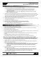
Using the LVC funcon with LiPo Baeries:
When using a LiPo baery with your vehicle, you must turn the LVC to “LiPo” to ensure the ESC will not
over-discharge the baery, causing damage and risk of re. Ensure you have the LVC set to “NiMH” when
using your vehicle with standard NiMH baeries.
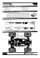
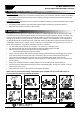
The Animus 18MT has been engineered with some available tuning opons listed here for reference.
Ride height adjustment: It is possible to adjust the ride height of your Animus 18MT by installing and or
removing adjustment clips located directly above the shock springs
• Adding more clips will raise the ride height of the vehicle and if done excessively may decrease stability.
• Removing clips will lower the ride height and may cause the chassis to drag on the ground.
• It is ideal to have the drive shas level with the ground while the vehicle is sing on a at surface with
the body installed. Add or remove clips to achieve the desired ride height
Shock Posion: There are two shock installaon locaons for the top mounng locaon of the shocks. The
default posion is inside (located closer to the centerline of the chassis)
• Moving the shock mounng locaon to the outer locaon will result in a slightly more responsive feel on
the front or rear of the vehicle
• Always check and adjust, if necessary, the ride height of your vehicle aer moving the shock mounng
locaons