
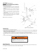
Replacement Part List
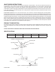
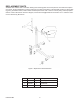


ASSEMBLY (See Figure 2)
Important: Reference Numbers are for assembly
puposes only. See replacement parts illustration for
ordering replacement parts.
1. Attach two wheels (Ref. # 1) to the front section (Ref.
# 14) with 3/8"x2-2/4"bolts (Ref. # 2)and3/8" nuts
(Ref. # 3).
2. Attach two casters (Ref. # 7) to the rear section (Ref.
#15)with1/4"x1/2"bolts(Ref.#8)and1/4"nuts(Ref.
# 6).
3. Attach the front section (Ref. # 14) and rear section
(Ref.#15)with1/2"x3-1/2"bolts(Ref.#4)and1/2"
nuts (Ref. # 5)
4. Attach four mounting arms (Ref. # 12) to head plate
(Ref.#9)with1/2"x2-1/4"bolts(Ref.#11),washers
(Ref. # 10) and nuts (Ref. # 13).
Note:AllboltsareratedGrade5.
5
OPERATION
1. Ensure application is compatible with product.
2. Align engine with engine stand, then adjust mounting arms to match bell housing mounting bolt holes. Rotation lock
must be secure before applying load.
3.Carefullysecureenginesothatloadiscenteredonstand.Securewithsuitablehighstrengthstudboltsandatwash-
ers. Ensurethreadsarecompatiblewithyourengine.Useatwasheronbothsidesofheadplate.
4. To rotate engine, loosen rotation lock bolt carefully. Use operating handle to rotate, then secure with rotation lock
bolt.
5. Check to ensure engine stand is secure before working on or around engine stand.
MAINTENANCE
Periodically inspect engine stand. Ensure all parts move freely. Apply very light coating of grease to head plate collar.
If rust appears, sand affected area and cover with suitable utility paint.
Figure 2. Assembly illustration
! WARNING
•Donotmoveloadedstandoffhardsmooth,level
surface !
•Never work under loaded engine stand.
HW93778-M0