Air Actuated Truck Jacks Operating Instructions & Parts Manual Model Number HW93731 HW93733 Capacity 20 Ton 20 Ton Made in the U.S.A. Model HW93733 Model HW93731 ! This is the safety alert symbol. It is used to alert you to potential personal injury hazards. Obey all safety messages that follow this symbol to avoid possible injury or death. SFA Companies 10939 N. Pomona Ave. Kansas City, MO 64153 customerservices@heinwerner-automotive.
! DANGER SIGNAL WORDS ! WARNING Indicates situation which, if not avoided, could result in death or serious injury Indicates situation which, if not avoided, will result in death or serious injury ! CAUTION NOTICE Indicates situation which, if not avoided, could result in damage to property Indicates situation which, if not avoided, could result in minor or moderate injury ! WARNING • Study, understand, and follow all instructions before operating this device. • Do not exceed rated capacity.
SPECIFICATIONS Model HW93731 Rated Load Capacity Model HW93733 20 tons (40,000 lbs) Rated Load Capacity 20 tons (40,000lbs) Low Pick Up Height 9-1/2" Low Height High Lifting Point 17-1/2" High Height With Extension Power Raise 5-1/2" Screw Extension 4 3/4" Screw Extension 2-1/2" Lift Cap Diameter 2" Base Size 8" x 5-1/2" 8" Chassis Overall Length 20" 2-3/16" Handle Length 50" Width at Wheels Wheel Diameter 6" Handle Length 150 psi Required Air Pressure For Lifting Loads 140
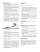
PREPARATION OPERATION Lifting 1. Verify that the product and the application are compatible, if in doubt contact Hein-Werner Technical Service (816) 891-6390. 2. Read the operator's manual completely and familiarize yourself thoroughly with the product and its components, and recognize the potential hazards associated with its use before using this product. 3. To familiarize yourself with the basic operation of the jack, locate and turn the release valve knob: a.
Adding Fluid 1. With saddle fully lowered, set jack in its upright, level position. Locate and remove oil filler screw. It may be necessary to remove cover plate on model HW93733. 2. Fill with hydraulic fluid until just below the rim of the oil filler hole. Reinstall oil filler screw. 2. When used on a daily basis, air pump should be internally lubricated before each use. Use only good quality air tool lubricant such as #630 - AAA Lubriplate.
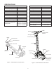
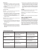
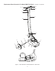
Replacement Parts Illustration For Model HW93731 (Part I) - ref page 8 for parts list 35 39 1 62 23 11 63 42 22 25 60 28 27 2 61 30 19 4 33 48 Air-Hydraulic Pump Assembly 34 (refer to Fig. 5) 39 39 52 Ram Assembly 5, 14 64 3 13 3 24 B 43 29 17 49 20 7 9 15 41 (refer to Fig. 4) B 37 59 A A 44 58 B 49 54 8 31 47 B 32 12 56 57 16 26 18 A Apply Never-Seez (or equivalent) to threads and face at both ends of Ram Cylinder (ref part #44) before assembling.
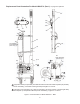
Replacement Parts Illustration For Model HW93731 (Part II) - ref page 8 for parts list 55 53 17 45 46 38 50 6 40 51 10 21 Figure 4 - Parts Illustration for Model HW93731 -Ram Assembly 95 88 96 93 94 77 Piston Assembly (refer to Fig. 6) 77 72 79 65 87 89 98 69 83 92 101 80 86 84 85 } 69 66 76 Figure 5 - Parts Illustration for Model HW93731 -Air Hydraulic Pump Assembly Thread into Piston to 73 dimensions shown 0.060" 0.
Replacement Parts List For Model HW93731 - ref pages 6 & 7 for parts drawing Item Part No.
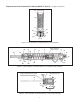
Replacement Parts Illustration For Model HW93733 (Part I) - ref page 11 for parts list 13 14, 15 12 16 17 11 18 10 3 9 4 1 3 3 2 5 6 19 7 8 Figure 7 - Parts Illustration for Model HW93733 - Main Frame 9
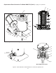
Replacement Parts Illustration For Model HW93733 (Part II) - ref page 11 for parts list 57 28 20 49 58 27 24, 25 52 53 47 37 29 44 26 34 54 35 41 36 55, 56 33 32 31 30 43 46 42 23 51 22 21 Hydraulic Unit Assembly (includes Air Motor) 64 65 63 62 38, 39 (in reservoir) 61 60 59 Model HW93733 Air Motor Figure 8 - Parts Illustration for Model HW93733 - Air Motor & Hydraulic Unit 10
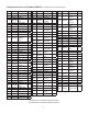
Replacement Parts List For Model HW93733 - ref pages 9 & 10 for parts drawings. Item Part No. Description Qty Item Part No. Description Qty 1 BK210980SF Top Cover 1 32* AJ100040 Valve Spring 1 2 BJ511626SF Frame Weldment 1 33* BB159167 Gaket, 19/32OD 1 3 BB557523SF Retaining ring, .94D 6 34* BK300600 Valve Plug 1 2 35 BK490010 Release Spindle 1 4 BE587106 Wheel, Rubber 8 x 2.
TWO YEARS LIMITED WARRANTY For a period of two (2) years from date of purchase, SFA Companies will repair or replace, at its option, without charge, any of its products which fails due to a defect in material or workmanship under normal usage. This limited warranty is a consumer's exclusive remedy. Performance of any obligation under this warranty may be obtained by returning the warranted product, freight prepaid, to SFA Companies Warranty Service Department, 10939 N. Pomona Ave., Kansas city, MO 64153.