LABOROTA 20 control automatic Betriebsanleitung Instruction Manual Mode d'emploi
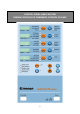
BEDIENFRONT BASISGERÄT CONTROL PANEL, BASIC SYSTEM PANNEAU FRONTAL DE COMMANDE, APPAREIL DE BASE 2
BEDIENFRONT DESTILLATIONSAUTOMATIK CONTROL PANEL, AUTOMATIC DISTILLATION PANNEAU FRONTAL DE COMMANDE, DISTILLATION AUTOMATIQUE 248 DEUTSCH Seite 4 - 63 ENGLISH page 64 - 124 D D E FRANCAIS page 125 - 186 F 3
D Wir danken Ihnen für den Kauf dieses Gerätes. Sie haben ein Produkt erworben, das von der Firma Heidolph Instruments nach DIN EN ISO 61010 gefertigt und geprüft wurde. Mit diesem Gerät werden Sie Ihre Arbeit einwandfrei und problemlos durchführen können. INHALT BEDIENFRONT BASISGERÄT..................................................................... 2 BEDIENFRONT DESTILLATIONSAUTOMATIK .......................................... 3 INHALT ..................................................................
D 13. Hauptschalter / Not-Aus Schalter .......................................................................... 27 14. Heizbadlift ................................................................................................................ 27 15. Drehzahleinstellung ................................................................................................ 28 16. Heizung .................................................................................................................... 29 17.
D 44. Verdampferkolben festziehen ................................................................................ 54 45. Funktion Kolbenentnahmevorrichtung ................................................................. 55 46. Vollautomatische Wassernachspeisung (nur Wasserbad) .................................. 56 47. Funktionen der Vakuumverteilung und Wasserverteilung .................................. 57 48. Temperaturfühler Pt100 Chiller ..............................................................
D LEGENDE: Wichtiger Hinweis Hinweis zur Anschlußleitung / Netzanschluß Achtung, unbedingt beachten Achtung, Brand- oder Explosionsgefahr Hinweis zur Reparatur / Wartung 8
D LIEFERUMFANG UND ZUBEHÖR Lieferumfang Folgende Einzel- und Zubehörteile werden geliefert. Inhalt der Lieferung mit dieser Liste vergleichen, bevor das Verpackungsmaterial beseitigt wird. Zum späteren Weitertransport oder einer Lagerung des Gerätes empfiehlt sich die grundsätzliche Aufbewahrung des Verpackungsmaterials.
D ZUBEHÖR (optional) Bezeichnung Bestellnummer Verdampferkolben 10 Liter 15-300-003-16 Pulverkolben 20 Liter 15-300-003-19 Pulverkolben 10 Liter 15-300-003-18 Unterbau zu LABOROTA 20 control 591-23000-00 Heizbadflüssigkeit 515-31000-00 ALLGEMEINE INFORMATION Bitte packen Sie das Gerät sorgfältig aus. Achten Sie auf mögliche Beschädigungen und melden Sie Schäden oder fehlende Teile unverzüglich dem Lieferanten.
D SICHERHEITSHINWEISE Bitte beachten Sie alle im Labor geltenden Sicherheits- und Unfallverhütungsvorschriften! Beim Betrieb von Rotationsverdampfern ist die erforderliche Sorgfaltspflicht anzuwenden. Während des Betriebes Augenschutz und geeignete Arbeitskleidung tragen. Äußerste Vorsicht beim Umgang mit leicht entzündlichen Medien. Beachten Sie die Sicherheitsdatenblätter.
D TECHNISCHE DATEN LABOROTA 20 CONTROL AUTOMATIC Anschlussspannung Anschlussleistung Rotationsdrehzahl (elektronisch geregelt) Heizbadbehälter Niveauregulierung Wasserbad Temperaturbereich Wasserbad Temperaturbereich Ölbad Heizleistung Heizbadlift Übertemperaturschutz und Trockengehschutz Anzeigebereich Siedetemperaturfühler Verdampferkolben Belüftungsventil, Vakuumventil und Vakuumsensor Timerfunktion Messbereich Vakuum Pumpleistung der Vakuumpumpe Kühlwasserbedarf Abmessungen ( Breite x Tiefe x Höhe ) Gew
D DESTILLATIONSHINWEISE 1. Allgemeine Hinweise Bei der Verwendung eines Rotationsverdampfers zur thermischen Stofftrennung sollten verschiedene Punkte beachtet werden, um bestmögliche Destillationsergebnisse zu erzielen. Für eine optimale Einstellung müssen folgende Parameter berücksichtigt werden: Drehzahl des Verdampfungskolbens Durch Erhöhung der Drehzahl läßt sich die Destillationsgeschwindigkeit steigern.
D 2.2. Vakuumregelmodus T auto Der Modus T auto zeichnet sich durch folgende Merkmale aus: Temperaturmeßfühler muss installiert sein Gemischdestillation ist ohne manuelle Anpassung des Druckes möglich Besonders hohe Wiederfindungsrate Einfache Einstellung Keine Kenntnis der thermodynamischen Stoffdaten notwendig besonders geeignet für umweltschonende bzw. verlustfreie Destillation Der Temperaturmeßfühler mißt bedingt durch seine Positionierung annähernd die Temperatur des Kühlmediums.
D Lösungsmittel Aceton Acetonitril C3H6O Benzol n-Butanol (Butylalkohol) tert.-Butanol (tert.-Butylalkohol) 2-Butanon (Methylethylketon) tert.
D INSTALLATION IM LABOR SICHERHEITSHINWEIS: DAS GERÄT IST NICHT EXPLOSIONSGESCHÜTZT. VORSICHT BEI DER ANWENDUNG IN DER NÄHE VON LEICHT ENTZÜNDLICHEN UND EXPLOSIVEN STOFFEN. DIE SPANNUNG DES GERÄTES (zusammen mit der Seriennummer auf der Rückseite des Gerätes zu finden) MUSS MIT DER NETZSPANNUNG ÜBEREINSTIMMEN. Das Gerät muss von einem Fachmann an Ihr Drehstromnetz angeschlossen werden.
D 5. Einbau des Dampfleitrohres und der Dichtung-PTFE Verschraubungen groß (1) und klein (2) abschrauben. Durch Drehen des Verriegelungsknopfes (3) 9 8 2 1 3 10 11 7 6 4 13 5 12 auf Rechtsanschlag (lock) wird der Antrieb blockiert und das Lösen und Festziehen der Verschraubung groß (1) bequem ermöglicht. PTFE-Formstück (4) mit integriertem PTFE-O-Ring (5) und Dichtung-PTFE (6) herausnehmen. Auflagering (7) und Dampfleitrohr (8) in Antriebskopf einführen.
D PTFE-Formstück (4) mit integriertem PTFE-O-Ring (5) in Antriebseinheit schieben. Verschraubung groß (1) über den Planflansch des Verdampferkolbens (12) aufschieben. Geschlitzten Einlagering groß (13) aufweiten und mit dem Absatz voran über den Planflansch des Verdampferkolbens (12) schieben. Auflagerohre der Kolbenentnahmevorrichtung in die markierten Raststellungen für 10 Liter oder 20 Liter bringen und durch Rechtsdrehung der Griffschrauben (14) fixieren. Markierung I = 10 Lit. ; II = 20 Lit.
D 7. Nach senkrechter Ausrichtung des Kühlers oder Expansionsgefäßes werden beide Flügelschrauben (2) festgezogen. Montage der Verschraubung KS 64 Die Verschraubung KS 64 (A) sichert die Verbindungen des Kühlers, des Expansionsgefäßes und des Vakuumstutzens (siehe Bild 1). Zur Montage Rändelschrauben (B) ganz nach oben Bild 1 A C Bild 2 D B A B schrauben.
D 9. Anschluss der PTFE Leitungen (G) 9.1 Einleitschlauch Zur Verbindung des Einleitschlauches PTFE (G) mit dem Einleitrohr (2) Schraubverbindungskappe (L) und den Klemmring (M) auf den Einleitschlauch PTFE (G) schieben (vgl. Bild Kap. 8). Schraubverbindungskappe (L) auf den Gewindestutzen des Einleitrohres (2) aufschrauben. D L;M;G 9.
D Achtung: Darauf achten, dass der zylindrische Körper des Not-Aus Sensors (11) im eingebauten Zustand waagerecht platziert ist. 11. Vakuum und Kühlwasseranschlüsse herstellen. 8 16 6 13 5 17 15 4 Auf der Rückseite des Gerätes befindet sich der Vakuum / Wasserverteiler. Der zentrale Kühlwasserverteiler versorgt Kühler T auto, Kondensatkühler und der Emissionskondensator der Vakuumpumpe mit Kühlflüssigkeit. Die Anschlüsse der Kühlwasserschläuche (di=8mm) erfolgt gem. Abbildung Seite 23.
D Achtung: Niemals im Kühlwasserrücklauf ein Ventil einbauen. Ein geschlossenes Ventil im Rücklauf baut in den Glaswendeln der Kühler hohe Drücke auf, die Glas bersten lassen.
D 11.1. Anschlussschema Vakuum und Kühlwasser Vakuum Kühlwasser 12. Elektrische Verbindung von Automaticmodul und Vakuumpumpe herstellen 1. Die elektrische Verbindung des Automaticmoduls wird an der Rückseite des Basisgerätes mit der speziell dafür vorgesehenen Steckdose mit Deckel, die sich in der Nähe des Netzanschlusskabels befindet, hergestellt. 2. Die elektrische Verbindung der Vakuumpumpe wird an der Steckdose in der Rückwand des Automaticmoduls hergestellt.
D GLASSATZ AUTOMATIC II 15-300-006-32 Einzelteile des Glassatzes A automatic II A B C D E F G H I I1 J K L M N O R S T U V W X Z 15-300-001-12 15-300-002-31 15-300-001-09 15-300-002-65 15-300-002-29 15-300-003-17 23-30-01-03-15 11-300-003-78 15-300-002-54 04-03-01-06-02 15-300-002-69 15-300-002-41 23-09-03-01-22 23-30-01-01-56 11-300-003-25 15-300-002-45 23-30-01-02-64 23-09-03-01-23 23-09-03-01-24 11-300-002-94 15-300-001-15 23-30-01-01-09 23-30-01-03-31 11-300-003-76 Kühler T auto (A) Vakuumstutzen Expa
D BETRIEB DES GERÄTES Der Einsatz von Rotationsverdampfern ist mit der erforderlichen Sorgfalt durchzuführen. Die im Labor geltenden Sicherheitsvorschriften sind zu beachten. Äußerste Vorsicht beim Umgang mit leichtentzündlichen Lösungsmitteln ist geboten. Die Motoren und Endschalter sind funkenfrei, doch wird keine Garantie dafür übernommen, dass das Gerät explosionssicher ist. SICHERHEITSHINWEIS: ACHTEN SIE DARAUF, DASS GERÄTE- UND NETZSPANNUNG ÜBEREINSTIMMEN.
D 26
D FUNKTIONEN DES BEDIENPANELS BASISGERÄT 13. Hauptschalter / Not-Aus Schalter Stop-Mode Not-Aus Schalter Hauptschalter Der Hauptschalter dient zur allpoligen Netztrennung des Gerätes und zum Reset des Gerätes nach Not-Aus. Der Not-Aus Schalter setzt bei Betätigung den Rotationsverdampfer still.
D Bei Überschreiten der maximal zulässigen Füllstandshöhe im Heizbad (ca. 30mm unter Heizbadrand, Überwachung mittels Niveauschalter) wird die Liftbewegung bei Lift auf automatisch gestoppt. Der Niveauschalter muss angeschlossen sein Wenn Wasser im Heizbad verdunstet, führt die Automatik das Heizbad in kleinen Schritten nach oben, bis die obere Endlage erreicht ist. Ist bei Erreichen der oberen Endlage der maximale Füllstand nicht erreicht, so wird automatisch Wasser nachgefüllt.
D 16. Heizung Display LED Act Bath LED Set Bath Taste Select Taste Start / Stop LED Act Chiller LED Heater LED Heater control Wert erhöhen Durch Drücken der Taste Select wird zwischen Displayanzeige Act Bath, Set Bath und Act Chiller umgeschaltet. Die jeweilige LED Act Bath, Set Bath und Act Chiller leuchtet. Act Chiller ist die aktuelle Kühlwassertemperatur. Sie wird für den Vakuumregelmodus T auto benötigt. Zur Einstellung der Heizbadtemperatur ist LED Set Bath anzuwählen.
D 18. Vakuumregelmodus p const In diesem Modus wird das Vakuum auf einem vorgewählten Wert gehalten. Mit Set Vakuum wird das Soll-Vakuum eingestellt und mit Set p das gewünschte p für die Regelung (Hysterese). Display LED Act Vacuum LED Set Vacuum Taste Select LED p Taste Start/Stop LED Ventilation LED Vacuum LED Valve ve Wert erhöhen Durch Drücken der Taste Select wird zwischen Displayanzeige Act Vacuum, Set Vacuum und Set p umgeschaltet. Die jeweilige LED Act Vacuum, LED Set Vacuum bzw.
D 19. Vakuumregelmodus T auto In diesem Modus wird das Vakuum über den Temperaturmessfühler aus dem Zubehörprogramm geregelt. Aufbau ist im Abschnitt Beschreibung Zubehör (Seite 59) beschrieben. T auto ist eine sehr umweltschonende Destillationsart. Durch diese sehr spezielle Art der Vakuumregelung werden nur geringste Mengen an Lösungsmitteln über die Vakuumpumpe abgesaugt. Der Temperaturfühler T auto misst inmitten der Kühlstrecke die Temperatur.
D Nach der Einstellung von Set T auto muss ein Enddruck eingegeben werden, nach dem die Destillation beendet wird. Im Display II erscheint nach 5 sec „EndP“, im Display I der vorher gewählte Wert für „EndP“. Nun mit den Set Tasten den gewünschten Enddruck einstellen. Der eingestellte Enddruck ist im Display I abzulesen. Display I Taste Select Display II Taste Start Stop 125 EndP Wird dieser Enddruck bei der Destillation erreicht, wird die Destillation abgebrochen.
D Display I Display II Taste Select Taste Start /Stop 750 1 CAL VAC Display Speed Display Time Mit Taste Start Stop bestätigen. Wert erhöhen Im Display I wird „50“ und in Display II „2“ angezeigt. (2. Schritt) Der LABOROTA 20 control automatic schaltet nun automatisch die Vakuumpumpe ein und evakuiert bis zur Beharrungsgrenze.
D 21. Auto Start Stop Mit der Taste Auto Start Stop wird die vollautomatische Destillation gestartet bzw. beendet. Vorher sind alle für die Destillation notwendigen Parameter einzugeben. Druck auf Taste Auto Start Stop setzt folgende Funktionen in Gang Lift auf Rotation ein Heizung ein Vakuumpumpe und Vakuumregelung aktiv Produktzuführung und Kondensatentnahme wird aktiviert Start der Zeitzählung (LED Act Time blinkt) LED Zur Bestätigung leuchtet die LED neben der Taste Auto Start Stop.
D Timer einschalten und starten Mit Taste Select Set Timer anwählen Gewünschte Zeit mit Set Tasten in Stunden und Minuten einstellen Timerfunktion mit Taste Start Stop starten, die LED Timer blinkt Im Display wird die Restzeit angezeigt. Nach Ablauf der eingegebenen Zeit wird die Destillation mit den oben beschriebenen Funktionen beendet. Timer einschalten und starten, wenn vorher mit Taste Auto Start Stop gestartet wurde: Taste Start Stop Timer Drücken, LED Set Timer leuchtet.
D Grenzwert verändern: LABOROTA 20 control mit dem Netzschalter „Power“ ausschalten. Taste Select und Taste Start Stop im Feld „Time“ gleichzeitig Drücken und Netzschalter „Power“ einschalten. Warten bis alle LED´s leuchten, dann Taste Select Taste Start Stop Taste Select und Taste Start Stop loslassen. Wert erhöhen Im Display I wird der momentan gültige Grenzwert z.B. 1100 mbar angezeigt. Dieser kann mit den Pfeiltasten verändert werden.
D Im Display II wird mit „ON“ oder „OFF“ angezeigt, ob die Sicherheitsabschaltung aktiv ist (ON) oder abgeschaltet (OFF) ist. Mit der Taste Mode kann zwischen „ON“ und „OFF“ gewechselt werden. Eine Abschaltung der Sicherheitsabschaltung ist nur in Ausnahmefällen zulässig! Es besteht die Gefahr der Beschädigung des LABOROTA 20 control! Der Vorgang muss mit dem ausschalten des Netzschalters „Power“ abgeschlossen werden. 24.
D Grenzwert: Je nach dem Sollvakuum, bei dem die Destillation ablaufen soll, kann es vorteilhaft sein, den Grenzwert anzupassen. Werksseitig ist der Grenzwert auf 900 mbar eingestellt, der Grenzwert kann zwischen 0 und 1200 mbar verändert werden. Achten Sie darauf, dass der Grenzwert nie niedriger eingestellt ist, als der Wert, bei dem die Destillation ablaufen soll, da sonst sofort „Emergency“ ausgelöst würde. Grenzwert verändern: LABOROTA 20 control mit dem Netzschalter „Power“ ausschalten.
D Im Display I (Vakuum) wird der momentan gültige Grenzwert z.B. 900 mbar angezeigt, der Grenzwert kann mit den Pfeiltasten verändert werden. Wert erhöhen Der Vorgang muss mit dem ausschalten des Netzschalters „Power“ abgeschlossen werden. Wert verringern 25. Sicherheitsfunktionen Leuchtet die LED Safety Cover ist die Haube geöffnet. Die Rotation kann nicht gestartet werden bzw. die Rotation stoppt. Die Haube ist zu schließen und Taste Start Rotation zu drücken.
D Die Heizung und Rotation stoppen. Das Vakuum wird abgeschaltet, System wird belüftet Ein Dauerton ertönt. Reset über Netzschalter aus und ein. ZEITFUNKTON UND RAMPENFUNKTION Die Zeitfunktion und Rampenfunktion erlaubt es, zeitliche Rampen zu den Werten für Badtemperatur und Drehzahl zu programmieren. Zu jedem Parameter sind maximal 10 Schritte programmierbar. Insgesamt sind maximal 20 Zeitpunkte programmierbar. 26.
Wert erhöhen Vakuum (Modus p const) LED Set Vacuum leuchtet T auto (Modus T auto) LED Set T auto leuchtet Badtemperatur LED Set Bath leuchtet Drehzahl LED Set Speed leuchtet Sollen von den oben angeführten Parametern einer oder mehrere nicht mit einer Rampenfunktion belegt werden, diese Parameter auf „OFF“ belassen. Die Einstellung des gewählten Wertes erfolgt, mit den Set Tasten. Durch erneutes drücken der Taste Select wird der Wert übernommen.
D Nach 5 Sekunden ohne Eingabe springt die Anzeige in den Act Zustand zurück. Der letzte Wert wird übernommen. Weitere Schritte: In gleicher Weise wie Schritt 2 können weitere Schritte programmiert werden. Bei umfangreichen Rampen empfehlen wir zur Planung die Verwendung des Vordruckes auf der folgenden Seite. Ein Beispiel ist ebenfalls auf der folgenden Seite dargestellt. Es können nur Werte programmiert werden, welche bei Zeit 00:00 aktiviert wurden.
Zeitpunkt Set Ramp Time Set Vac Set T auto Set Bath Set Speed Einheit hh:mm mbar °C °C rpm 1 2 3 4 5 6 7 8 9 10 Zeitpunkt Set Ramp Time Set Vac Set T auto Set Bath Set Speed Einheit hh:mm mbar °C °C rpm 11 12 13 14 15 16 17 18 19 20 Zeitpunkt Set Ramp Time Set Vac Set T auto Set Bath Set Speed Einheit hh:mm mbar °C °C rpm 21 22 23 24 25 26 27 28 29 30 Zeitpunkt Set Ramp Time Set Vac Set T auto Set Bath Set Speed Einheit hh:mm mbar °C °C rpm 31 32 33 34 35 36 37 3
Beispiel: Zeitpunkt Set Ramp Time Set Vac Set T auto Set Bath Set Speed Einheit hh:mm mBar °C °C rpm 1 0:00 1000 OFF 20 30 2 0:15 1000 3 0:20 700 4 0:30 400 5 0:40 200 6 0:50 150 7 1:00 100 50 30 8 2:00 10 60 50 1200 70 1000 60 50 800 40 600 30 400 20 200 10 0 0:00 9 0 0:15 0:30 0:45 1:00 1:15 44 1:30 1:45 2:00 2:15 2:30 2:45 3:00 Set Vac Set Bath Set Speed
D 27. Rampenwerte anzeigen Die programmierten Rampenwerte können angezeigt und verändert werden. Taste Ramp drücken; LED Ramp on leuchtet. Durch mehrmaliges Drücken der Taste Select (Time) ist LED Set Ramp Value anzuwählen. Als erstes wird der Zeitpunkt 00:00 und die dazugehörigen programmierten Werte angezeigt. Nichtprogrammierte Parameter sind mit OFF gekennzeichnet. Mit Set Tasten können weitere Zeiten mit den dazugehörigen Werten angezeigt werden. 28.
D FUNKTIONEN DES AUTOMATICMODULS Die Automatisierung des LABOROTA 20 control automatic ist durch folgende Komponenten realisiert: Automatische Nachdosierung von Produkt o Produkt wird über Unterdruck in den Verdampferkolben eingesaugt. o Über das Magnetventil Produkt wird aus dem Produkt-Gefäß in den Verdampferkolben nachdosiert. o Ein Gewichtssensor überwacht minimale und maximale Füllung des Verdampferkolbens. Minimale und maximale Füllung des Verdampferkolbens sind vom Anwender einfach justierbar.
D 47
D 32. Befüllung des Verdampferkolbens 32.1. Gewichtssensor Im Antriebskopf des LABOROTA 20 ist ein Gewichtssensor untergebracht, der das Gewicht des Verdampferkolbens samt Inhalt bestimmen kann. Somit ist es möglich, den Verdampferkolben immer bis zu einem bestimmten Gewicht zu befüllen und die Wiederbefüllung bei einem bestimmten Minimumgewicht auszulösen.
D Niveausteuerung ausgestattet ist, wird die Füllhöhe in engen Grenzen konstant gehalten. Dadurch ist beim Wasserbad der Einfluss der Füllhöhe gering. Beim Ölbad ist durch die fehlende Nachspeisung das Niveau des Flüssigkeitsspiegels vom Anwender, der das Heizbad befüllt hat, abhängig. Wichtig ist, dass die Wärmeausdehnung von Öl oder Heizbadflüssigkeit beachtet wird. Der betriebsmäßige Auftrieb stellt sich erst ein, wenn die eingestellte Solltemperatur des Heizbades erreicht ist. 32.2.4.
D 31.5. Einstellung der minimalen Füllmenge 32.5.1. Taste Set min Level drücken (Kontrollleuchte Set min Level leuchtet), im Display wird der Grenzwert angezeigt, der mit dem min Poti verändert werden kann. 32.5.2 Einen um ca. 10 – 50 Einheiten niedrigeren Wert als bei Set max Level mit kleiner Münze am min Poti einstellen. 32.5.3 Die automatische Produkt Zudosierung wird nun immer bei Erreichen dieses Wertes aktiviert. 33.
D 35.2. Abbruch durch Timer Ist die vorher eingestellte Timerzeit abgelaufen, bricht die Destillation mit folgenden Aktionen ab: Lift ab Rotation aus Heizung aus Belüftungsventil auf, Vakuumregelung aus und Vakuumpumpe aus Produktzuführung und Kondensatentnahme wird gestoppt Signalton für 10 sec ein 35.3.
D Vor Reset und erneutem Start unbedingt Ursache der Störung beseitigen. SCHNITTSTELLE 38. Anschluss der Schnittstelle Schalten Sie vor dem Anschluss des Schnittstellenkabels das Gerät aus. Zum Anschluss der Schnittstelle verwenden Sie bitte ein Schnittstellenkabel mit SUB-D 9 Steckern und schließen es an die Buchse unterhalb des Bedienpultes des LABOROTA 20 control automatic an. 39. Schnittstellenparameter 9600 Baud, No Parity, 8 Bit, 1 Stopbit, kein Protokoll 40.
D Ansteuerung Befehl Aktion Bemerkung VAC=XXXX! Set Vacuum 4 stellig in mbar; Einstellbereich 0000 bis 1200 BATH=XXXX! Set Bath 4 stellig mit einer Kommastelle in 1°C Schritten Einstellbereich 0000 bis 1800 für 0,0 bis 180,0 SPEED=XXX! Set Speed 3 stellig in rpm; Einstellbereich 000 bis 180 TIME=XXXX! Set Timer 4 stellig in hh:mm; Einstellbereich 0000 bis 9959 für 00:00 bis 99:59 SVX! Start Stop Vacuum SV0! = Aus ; SV1! = Ein VVX! Valve Schalten Vakuumventil; VV0! = Zu ; VV1! = Auf BVX!
D Blockiervorrichtung einrücken: Verriegelungsknopf (8) auf Rechtsanschlag drehen (lock). Antriebskopf verdrehen, bis Blockierung einrastet. LED Rotation Stop an der Bedienfront leuchtet. Blockiervorrichtung ausrücken: Verriegelungsknopf (8) auf Linksanschlag drehen (unlock). LED Rotation Stop an der Bedienfront erlischt. 44. Verdampferkolben festziehen Der Verdampferkolben muss mit der Verschraubung groß (X) ausreichend festgezogen werden.
D 45. Funktion Kolbenentnahmevorrichtung 8 1 2 4 5 7 Die Kolbenentnahmevorrichtung erlaubt es auch, gefüllte Rotationskolben (1) bequem von einer Person entnehmen oder montieren zu lassen. 1. Kolbenentnahme: Schutzhaube (2) öffnen. Blockiervorrichtung (8) einrücken. Auflagerohre (4) der Kolbenentnahmevorrichtung von links und rechts an den Rotationskolben (1) führen, bis diese anliegen. Beide Auflagerohre durch Rechtsdrehen der Griffschrauben (5) fixieren (auf Festsitz der Griffschrauben achten).
D 46. Vollautomatische Wassernachspeisung (nur Wasserbad) Der LABOROTA 20 control WB ist mit einer vollautomatischen Wassernachspeisung mit Niveauschalter ausgestattet. Ein Niveauschalter (1) überwacht den Wasserstand des Heizbades. Bei unterschreiten des Wasserniveaus (ca. 30mm unter Heizbadrand) wird über das Magnetventil (12) (nächster Abschnitt) solange Wasser nachdosiert, bis das Standardniveau erreicht ist. Das Kühlwasser wird über ein Rohr zum Heizbad geführt.
D 47. Funktionen der Vakuumverteilung und Wasserverteilung 11 10 8 9 12 7 16 6 13 5 17 15 4 Auf der Rückseite des Gerätes befindet sich der Vakuum / Wasserverteiler. Bei zentralem Kühlwasseranschluß können wahlweise 1 Kühler; 1 Kühler und 1 Nachkühler; oder 2 Kühler mit Kühlflüssigkeit versorgt werden. Die Anschlüsse der Kühlwasserschläuche (di=8mm) erfolgt gem. Abb. oben.
D 48. Temperaturfühler Pt100 Chiller Der Temperaturfühler Pt100 Chiller muss am entsprechenden Steckplatz (1) angeschlossen werden. Dieser Temperaturfühler ist für die Anzeige der Kühlwassertemperatur Act Chiller verantwortlich 1 FUNKTION UND HANDHABUNG HEIZBAD 49.
D 51. Kondensatabführung (nur bei Wasserbad) 2 Der LABOROTA 20 control hat in der Wasserbadversion eine Kondensatabführung. Kondenswasser, das bei hohen Badtemperaturen durch die Wasserbadfüllung entsteht, tropft am mit Kühlschlangen (1) gekühlten Kondensator (2) ab und wird in der Auffangrinne (3) gesammelt und über die Schlaucholive (4) nach außen geführt. An der Schlaucholive (4) ist ein elastischer Schlauch (di = 8 mm) anzuschließen, dessen Ende in ein Auffanggefäß gelegt wird. 1 3 4 52.
D 3 4 54. Temperaturfühler für Vakuumbetriebsart T auto Der Temperaturfühler (5) (Zubehör 14-014-00306) wird für die Betriebsart Vakuumregelmodus T auto benötigt. Um ihn anzuschließen, wird die Verschlußkappe am Kühler (6) entfernt und an seiner Stelle der Temperaturfühler eingeschraubt. Im Vakuumregelmodus T auto ist der Anschlußstecker des Temperaturfühlers in die vordere Steckbuchse (4) auf der Rückseite des Antriebskopfes zu stecken.
D REINIGUNG UND WARTUNG Zur Reinigung können Sie das Gehäuse und die Oberfläche des Gerätes mit einem feuchten Tuch (milde Seifenlauge) abwischen. Hinweis Verwenden Sie auf keinen Fall Chlorbleiche, auf Chlorbasis aufbauende Putzmittel, Scheuermittel, Ammoniak, Putzwolle oder Reinigungsmittel mit metallischen Bestandteilen. Die Oberfläche des Gerätes kann dadurch beschädigt werden. Bei längerem Gebrauch auftretende Rostpunkte am Boden des Heizbades sind durch Ablagerung von Fremdstoffen (Eisenpartikel bzw.
D ENTSORGUNG Bitte entsorgen Sie Altgeräte bzw. defekte Geräteteile fachgerecht bei einer Sammelstelle. Trennen Sie bitte auch das Altmaterial in Metall, Glas, Kunststoff usw. Auch das Verpackungsmaterial sollte umweltgerecht (Materialtrennung) entsorgt werden.
D Destillation wird automatisch ungewollt abgebrochen Wert EndP falsch eingestellt; Timerwert Set Time falsch eingestellt, Not-Aus Sensor hat angesprochen Siehe auch Kapitel Sicherheitsfunktionen (Seite 39) Sollte eine Störung auftreten, die Sie mit den oben genannten Hinweisen nicht beseitigen können, informieren Sie bitte unverzüglich Ihren autorisierten Heidolph Instruments Händler.
D FRAGEN / REPARATUREN Haben Sie nach dem Lesen der Betriebsanleitung noch Fragen zu Installation, Betrieb oder Wartung, wenden Sie sich bitte an die im folgenden genannte Adresse. Bei Reparaturen wenden Sie sich bitte vorab telefonisch an Heidolph Instruments direkt (Tel.: 09122/9920-69) oder an Ihren autorisierten Heidolph Instruments Händler. Hinweis Bitte senden Sie Geräte ausschließlich nach vorheriger Rücksprache an diese Anschrift: Heidolph Instruments GmbH & Co.
E Thank you for buying a Heidolph Instruments product. This unit has been designed, made and inspected in compliance with DIN EN ISO 61010 for long-term and flawless operation. SUMMARY CONTROL PANEL, BASIC SYSTEM ........................................................... 2 CONTROL PANEL, AUTOMATIC DISTILLATION ....................................... 3 SUMMARY .................................................................................................. 65 PARTS AND ACCESSORIES SUPPLIED ...............
E 14. Heating bath lift ....................................................................................................... 87 15. Speed setting ........................................................................................................... 88 16. Heater ....................................................................................................................... 89 17. Select vacuum control mode ..................................................................................
E 45. Flask supports ....................................................................................................... 114 46. Automatic water refill (water bath model only) ................................................... 115 47. Vacuum and water distribution ............................................................................ 116 48. Pt100 temperature sensor, chiller ........................................................................ 117 HEATING BATH FUNCTION AND HANDLING ..........
E PARTS AND ACCESSORIES SUPPLIED Scope of supply Your LABOROTA 20 cartons contain the parts and accessories as listed below. Before disposing of the carton, check the contents for all items on the below parts list. We recommend to keep packing material for future use. Item P/N LABOROTA 20 S A control automatic qty.
E Accessories (optional) Item P/N 10 l evaporator flask 15-300-003-16 20 l powder flask 15-300-003-19 10 l powder flask 15-300-003-18 Base cart for LABOROTA 20 control 591-23000-00 5 liters bath liquid 515-31000-00 GENERAL Unpack your LR20 control automatic carefully. Inspect for damage and report such damage or missing parts to your supplier right away. Read your Instruction Manual thoroughly. Make sure that every user has read and understood the Instruction Manual.
E SAFETY INFORMATION Please comply with all safety and accident-prevention regulations, as in force for laboratory work ! Use extra care when working with rotary evaporators. Use adequate eye protection and protective garments. Use extra care when working with flammable substances; refer to safety data sheets. When connecting your unit with your local power supply, please make sure your unit is designed for your local supply voltage; go by data plate on the unit.
E LABOROTA 20 CONTROL AUTOMATIC, SPECIFICATIONS Supply voltage Power rating Rotation speed (electronic control) Heating bath Level control, water bath Temperature range, water bath Temperature range, oil bath Heating power Bath lift Over temperature & dry running protection Boil temp.
E REMARKS ABOUT DISTILLATION 1. General Using rotational evaporators for thermal breakdown of substances needs some basic considerations about optimizing the distillation process. Parameters stipulated below are to be considered for making optimal settings. Rotational speed, evaporator flask Increasing rotational speed will increase rate of distillation. Shorter distillation time preserves thermal stability of your substances to be distilled.
E The T auto mode includes the following features: (Temperature sensor needs to be installed) Selective distillation of substances does not need manual pressure setting Easy to reproduce Easy setting No need to know about thermodynamic substance data first choice for low-pollution / zero-loss distillation. Due to its location, the temperature sensor detects coolant temperature as an approximate only. Set T auto values of 2 – 8°C above coolant temperature for optimum reproducibility.
E Solvent Aceton Acetonitril Total formula C3H6O Benzol n-Butanol (Butylalkohol) tert.-Butanol (tert.-Butylalkohol) 2-Butanon (Methylethylketon) tert.
E LABORATORY SET-UP SAFETY INFORMATION: THIS APPLIANCE IS NOT EXPLOSION-PROOF. USE EXTREME CARE WHEN USING IN THE VICINITY OF FLAMABLE OR EXPLOSIVE SUBSTANCES. When connecting this product with your local power supply, make sure you got the right thing ! Check VOLTAGE DATA on DATA PLATE (located in the rear). This product has to be wired with your local 3-phase network by a skilled electrician.
E SET-UP Carefully unpack all parts, inspect for missing parts by packing list. 4. Set-up 6 The LABOROTA 20 control with its transportation rods is bolted to the pallet. Remove these screws and carry the unit to its place of installation (CAUTION: 2 persons needed; in this configuration, unit’s weight is about 110 kg). Place the LABOROTA 20 control on a stable level stand.
E 5. Install vapor tube and PTFE-seal Unscrew large-size (1) and small (2) coupling rings. Lock driveshaft by turning drive lock (3) 9 8 2 1 3 10 11 7 6 4 13 5 12 clockwise (lock) to ease loosening and tightening of large-size ring (1). Remove PTFE-adapter (4) with built-in PTFE-O-ring (5) and PTFE-seal (6) Install backing ring (7) and vapor tube (8) in drive head. Put sandwich gasket (9) on vapor tube coupling flange Slide small ring (2) over coupling flange of distributor (10).
E Screw large-size ring (1) tight. When evacuating, double-check for firm seat. Refer to page 113 Return flask lift support tubes to initial position (16), CAUTION: basic position uses electronic monitor circuit. Leaving this position will freeze all electric functions of the LABOROTA 20 control. This situation is reported by an LED on the control panel (flask support). 6.
E 7. Assembly of screw joint KS 64 The screw joint KS 64 (A) secures the connections of cooler, expansion vessel and vacuum connector (ref. Fig. 1). For assembly screw knurled screws (B) to top. Like indicated in Fig. 2, press knurled screws (B) down and slide screw joint onto glass joint (C). Fasten knurled screws (B) like indicated in Fig 1. Fig 1 A C Fig 2 D B A B Attention: Make sure that washer (D) is installed properly. White PTFE cover must face towards the pan of the connection. 8.
E 9. Connection of PTFE tubing (G) 9.1 Inlet tube For the connection of the inlet tube (G) with inlet pipe (2) slide on screw cap (L) and locking ring (M) on the feeding tube (G). Screw cap (L) on inlet tube (2). D L;M;G M L G 9.2 Venting tube: condensate cooler – glass set For connection of venting tube with elbow of the glass set slide on screw cap (L) and locking ring (M) on venting tube (G). Screw cap (L) on screw connector. 10.
E 11. Connection of vacuum and cooling water tubing. 8 16 6 13 5 17 15 4 The rear panel of the unit contains a vacuum / water distributor. The central water distributor supplies the cooler T auto, the condensate cooler and the emission condenser of the vacuum pump with cooling water. Refer to picture (page 83) when connecting the water hoses (ID=8 mm). They are installed within the cooler housing and connected to the cooler via screw connector.
E Attention: Never install a valve in main return line of cooling water. A closed valve leads to pressure build-up in the glassware which can lead to damage of glass.
E 11.1. Connection scheme vacuum and cooling water vacuum cooling water 12. Electric wiring between automatic module and vacuum pump 1. 2. 3. Connect automatic module with terminal box (with cover) located on the rear panel of the basic item, close to the power cord fairlead. Connect vacuum pump with outlet in the rear panel of the automatic module. Turn vacuum pump's power switch to "ON".
E GLASS-SET –A AUTOMATIC II 15-300-006-32 Components of the "A" automatic II glassware kit A B C D E F G H I I1 J K L M N O R S T U V W X Z 15-300-001-12 15-300-002-31 15-300-001-09 15-300-002-65 15-300-002-29 15-300-003-17 23-30-01-03-15 11-300-003-78 15-300-002-54 04-03-01-06-02 15-300-002-69 15-300-002-41 23-09-03-01-22 23-30-01-01-56 11-300-003-25 15-300-002-45 23-30-01-02-64 23-09-03-01-23 23-09-03-01-24 11-300-002-94 15-300-001-15 23-30-01-01-09 23-30-01-03-31 11-300-003-76 condenser, T auto (A) vac
E WORKING WITH THE LABOROTA 20 CONTROL Use rotary evaporators with appropriate care. Comply with standard laboratory safety practices. Be cautious when working with flammable solvents; motors and limit switches are of non-sparking type but we cannot guarantee that the unit is explosion-proof. SAFETY INFORMATION: WHEN CONNECTING YOUR UNIT WITH YOUR LOCAL POWER SUPPLY, PLEASE MAKE SURE YOUR UNIT IS DESIGNED FOR YOUR LOCAL SUPPLY VOLTAGE; GO BY DATA PLATE ON THE UNIT.
E solenoid valve scavening vacuum pump solenoid valve scavening air reflux aperture aftercooler produkt - sensor fitting cooling water separator 86
E CONTROL PANEL 13. Master switch / EMERGENCY-CUT-OUT Stop-Mode Stop-Mode Emergency CUT-OUT Master switch The Master switch disconnects all wires from power supply, and serves as a RESET button. (after Emergency CUT-OUT). The Emergency CUT-OUT discontinues operation of the rotary evaporator immediately.
E Exceeding the max. fill mark (about 30 mm below tank rim, monitored by float switch), the Lift UP motion is discontinued automatically. float switch must be connected As water in the heating bath evaporates, the heating bath itself travels up in small increments for compensation, until reaching the upper stop. If max fill level is not sensed at the upper stop, the water will be refilled automatically. Oil bath only: The LABOROTA 20 control automatic OB (oil bath) features neither refill or float switch.
E 16. Heater Display Act Bath LED Set Bath LED Select key Start / Stop key Act Chiller LED Heater LED Heater control LED LEDLED Change between Act Bath, Set Bath and Act Chiller with increase Select key. Act Bath, Set Bath or Act Chiller LED turns ON. Act Chiller is the actual coolant temperature, which is the basis for the T auto vacuum control mode. To set heating bath temperature, select Set Bath LED. Display now shows the heating bath’s nominal temperature with a 1/10 of a degree C resolution.
E 18. P const vacuum control mode In this mode, a vacuum level once selected will be maintained. Set Vacuum key sets the level and Set p your control span p (hysteresis) Start Stop key Display Act Vacuum LED Set Vacuum LED Select key p LED Aeration LED LED Vacuum Valve LED increase Change between Act Vacuum, Set Vacuum and Set p with Select key. Act Vacuum LED, Set Vacuum LED, or Set p LED will illuminate. Select Set Vacuum LED for setting the nominal vacuum level.
E Set T auto is set to 2 – 10 °C (temperature difference from cooling water). A high Set T auto value results in high-speed distillation, whereas a low value renders a slow and controlled distillation process. When reaching the temperature difference (in the condenser) once set with Set T auto, the vacuum valve closes; as soon as the temperature drop equals Set Vapor (hysteresis), the valve will open once more. A current Set Vapor setting is 0.5°C.
E Reaching this final pressure during distillation, will discontinue distillation right away. Also refer to Display I Display II Taste Select Taste Start Stop 125 EndP Auto Start Stop function (see page 94) If distillation should not be discontinued, enter "1" in "Endp mode", which never can be reached by physical condition. For hysteresis setting select LED Vapor. Use Set keys as required 20.
E Display I Display II Select key Taste Start /Stop 750 1 CAL VAC Display Time Display Speed Turn vacuum pump ON Turn LABOROTA 20 control automatic Master switch (Power) OFF Depress Select and Start Stop keys next to display I together and hold for 5 seconds, turn master switch ON, release keys Display Speed shows “CAL”, display Time “VAC”.
E Calibration is complete Unplug power plug of vacuum pump from socket on backside of base unit and plug it into automatic module (original state) Unplug power plug of automatic module and plug it into socket on the backside of the base unit (original state) 21. Auto Start Stop With Auto Start Stop fully automatic distillation is started or stopped.
E 22. Timer Select key Display Act Time LED Set Ramp Time LED Set Time LED Start Stop key Set Ramp Value LED Timer LED The timer function allows ending distillation after a pre-selected period of time has expired. After the time has elapsed, the following actions will be taken: increase Lift DOWN Rotation OFF Heater OFF Aerating valve OPEN, vacuum control OFF and vacuum pump OFF.
E Description: A vacuum sensor, installed to display and regulate distillation pressure, monitors pressure in the glassware kit either. Pressure rise above e.g. 1,100 mbar will disconnect the LABOROTA 20 control by activating the „Emergency“ function: Hot bath lift rises automatically, heater and rotation are disconnected, vacuum controller off, aeration valve open and vacuum pump off, system is aerated, a buzzer sounds continuously, Emergency LED lights, Akt Vacuum LED flashes.
E Do not override this safety feature except in very rare cases ! Your LABOROTA 20 might be damaged ! Display I Display II Mode key Confirm this action by turning the power switch OFF. 24. Safety cut-off in case of a defect in the vacuum system The LABOROTA 20 control has a special monitoring function for the vacuum. Disconnected vacuum hoses, broken glass parts, defective vacuum pump, and lack of vacuum from the central vacuum supply are recognized during distillation.
E Limit value: Depending upon the desired vacuum, at which distillation should occur, it can be advantageous to adjust the limit value. From the factory, the limit value is set at 900 mbar. The limit value can be changed from 0 to 1200 mbar. Pay attention that the limit value is never set lower than the value, at which distillation should occur, as an „Emergency“ will be triggered otherwise. Change limit value: Switch off the LABOROTA 20 control with the master switch „Power“.
E Display I Display II Mode 900 ON SAFE Display Speed Select key Start /Stop key release the Select key and the Start Stop key. „SAFE“ appears in the Display Speed Whether or not the safety cut-off is active (ON) or switched off (OFF) is shown in Display II (Temp Vapour) with „ON“ or „OFF“. You can change from „ON“ to „OFF“ with the Mode key. Switching off the safety cut-off is the sole responsibility of the user.
E 25. Safety functions All of the following cause LED ON situations. The Safety Cover LED tells you that the enclosure is open. Rotation won’t start, or rotation is going to stop. Close hood and hit Start Rotation key. Flask Support LED : Flask support is not in its extreme position (either side). Rotation won’t start, or rotation is going to stop, lift won’t work. Move flask support to extreme position (both sides) and secure with knurled knobs (7, page 114).
E Select key Display Act Time LED Set Time LED Start Stop key Set Ramp Value LED Set Ramp Time LED Timer LED 26. Set ramp values Before programming a new ramp, make sure to have deleted the old one (refer to “delete ramp”, page 105). Procedure 1st step: You need to program 00:00 for the first time. Press the Select key next to the Display Time until Set Ramp Time LED illuminates. Set Ramp Time LED ON. Display Time only is active, all other displays are blank.
E key Select for Set Vacuum using p const OFF key Select for Set ΔT auto using T auto OFF OFF key Select for OFF key Select for Set Bath Set Speed 00:00 2nd step: Now, select the LED Set Ramp Time by pressing the Select key next to Display Time repeatedly. The time for the 2nd step of programming can be changed with the Set increase or Set decrease keys. After 5 seconds with no entry, the display returns to Act Condition. The last value is accepted.
Time Set Ramp Time Set Vac Set T auto Set Bath Set Speed Unit hh:mm mbar °C °C rpm 1 2 3 4 5 6 7 8 9 10 Time Set Ramp Time Set Vac Set T auto Set Bath Set Speed Unit hh:mm mbar °C °C rpm 11 12 13 14 15 16 17 18 19 20 Time Set Ramp Time Set Vac Set T auto Set Bath Set Speed Unit hh:mm mbar °C °C rpm 21 22 23 24 25 26 27 28 29 30 Time Set Ramp Time Set Vac Set T auto Set Bath Set Speed Unit hh:mm mbar °C °C rpm 31 32 33 34 35 36 37 38 39 40 103
example: Time Set Ramp Time Unit hh:mm Set Vac Set T auto Set Bath Set Speed mbar °C °C rpm 1 2 3 0:00 1000 OFF 20 0:15 1000 20 30 4 0:20 700 5 0:30 400 6 0:40 200 7 0:50 150 8 1:00 100 9 2:00 50 1200 70 1000 60 50 800 40 600 30 400 20 200 10 0 0:00 10 0 0:15 0:30 0:45 1:00 1:15 1:30 1:45 104 2:00 2:15 2:30 2:45 3:00 Set Vac Set Bath Set Speed
E 27. Display ramp values Ramp values once programmed can be displayed and edited. Hit Ramp key; Ramp on LED illuminates. Press the Select key (Time) until Set Ramp Value LED illuminates. First programmed time 00:00 and corresponding value are displayed. Void parameters are marked OFF. More times and programmed values are displayed with the Set keys. 28. Edit ramp values To edit a value, select with Select key. Now edit value with the Set keys. Accept new value by pressing the Select key once more.
E AUTOMATIC MODULE FUNCTIONS LABOROTA 20 control automatic features the following control components: Automatic product refill o Product is sucked into evaporator flask by vacuum pressure. o Refill system for the evaporator flask features solenoid valve for product tank. o A weight sensor is monitoring min. and max. fill of the evaporator flask. Both parameters are easy to adjust by the user. o A product sensor monitors availability of the product in its feed line.
E produkt - sensor aftercooler fitting cooling water separator 107
E 32. Fill evaporator flask 32.1 Weight sensor The LABOROTA 20 drive head features a weight sensor to determine weight evaporator flask and its contents. This way, evaporator flask can be filled to a certain mass all the time and start refill at a certain weight defined before. Weight is displayed as „Solvent Level“, figure displayed being relative, instead of the absolute weight in kg. 248 32.2. Accuracy of weight displayed Weight displayed is a function of a variety of factors and may differ: 32.2.1.
E 32.2.4. Evaporator fill level The more fluid filled in the evaporator flask, the higher the Solvent Level displayed is. 32.2.5. Display: hot bath in low position Descending the hot bath, buoyancy in the hot bath fluid won't exist; hence, weight displayed under Solvent Level will be higher ! For reproducible fill levels, it will be of essence to run the hot bath against its upper mechanical stop all the time ! 32.3.
E 33. Distillation cycle Distilling off, Distilling LED will light; feeding product is confirmed by the Refilling LED. 34. End of product metering Product tank empty, a product sensor will trigger a solenoid valve in the product feed line. From this moment on, the product can be distilled to whatever degree, as requested by the user. 35. End of distillation When reaching concentration wanted, distillation needs to be discontinued.
E To this end hit Pump ventilation key. Pump ventilation LED is lighting. After about a couple of minutes, stop this operation by hitting the Pump ventilation key once again. 37. Cut-out-sensor Automatic distillation is supervised by cut-out-sensor (X). If a failure in the automatic discharging unit occurs and the condensate can’t flow into the condensate cooler, the Yconnection (J) will fill up with condensate.
E 41. RS 232 interface commands query Command action remarks Act commands VAC? Act Vacuum VAP? Act Vapor BATH? Act Bath CHILL? Act Chiller SPEED? Act Speed TIME? Act Time elapsed time, continuous operation COUNT? Safety functions Act Time time, timer mode SC? Safety Cover 0 = action; 1 = no action FS? Flask Support 0 = action; 1 = no action RS? Rotation Stop 0 = action; 1 = no action OP? OverTemperature Prot.
E FUNCTIONS AND HANDLING 42. Protective enclosure 8 The protective enclosure (1) is an extra safety feature for the operator. Its large pane of a special safety glass guarantees a clear view of the rotating flask. A handle (2) on the front is used for closing and opening. In both extreme positions, it is held by a pneumatic strut. Caution: Flask will not rotate unless the hood is closed. Opening the enclosure during operation will stop rotation. Safety Cover LED (6) illuminates.
E X Z Y A 45. Flask supports 8 1 2 4 5 7 The flask supports make flask (1) removal (even filled) an easy job for one person. Uninstall flask: Open enclosure (2). Engage drive lock (8). Slide support pipes (4) to flask (1) from both sides. Check for firm contact and lock support pipes in place by tightening thumbscrews (5) CW. Unscrew large coupling ring (6, not shown) by turning CCW. Tilt flask neck with large coupling ring (6) forward.
E large coupling ring (6), on support pipes carefully. Swing flask axis with coupling ring in-line with axis of rotation, until flange is centered in drive head. Secure PTFE-adapter (not shown) with PTFE-O-ring tight by CW turn. Double-check for firm seat. Return support pipes to initial position (7). Release drive lock (3). Caution: Basic position of support pipes is monitored by the electronic circuit; when leaving this position, all electric functions of the system will freeze.
E 47. Vacuum and water distribution 11 10 8 9 12 16 6 13 15 5 17 4 The rear panel of the unit contains a vacuum/water distributor. A central cooling water supply optionally works with: 1 chiller; 1 chiller plus 1 after-chiller, or 2 chillers. Refer to picture above when connecting the water hoses (ID=8 mm). Hoses are routed in the chiller panel and attached to the chiller with hose nipples. Inlet flow control uses a ball valve (4).
E 48. Pt100 temperature sensor, chiller The chiller Pt100 sensor is connected with the terminals (1); this sensor used to display cooling water temperature (Act Chiller).
E HEATING BATH FUNCTION AND HANDLING 49. Fill heating bath (water bath only) Using de-ionized or distilled water needs to add 0.2 % of Borax (Na2B4O7*10H2O) (corrosion inhibitor) Please note: The use of tabwater as heating media can lead to calcification which can provoke crevice corrosion.Therefore the user is strongly recommended to clean the heating bath with an adequate polish on a regular basis. Heating bath water supply uses the vacuum/water distributor (refer to page 116).
E Descend heating bath lift to LOW. Turn master switch OFF. Reset over temperature protector by introducing an insulated screwdriver through the little hole at the lower right end of the unit. (remove black plastic plug to gain access through panel) OPTIONS 1 53. Temperature sensor for vapor To display vapor temperature on the control panel, you’ll need the optional temperature sensor (1) (P/N 14-014-003-06). To install, remove cap from temperature fitting (2) of glass kit.
E 54. Temperature sensor for T auto vacuum mode T auto vacuum control mode needs the optional temperature sensor (5) (P/N 14-014-003-06). To install, remove caps from condenser (6). When running the T auto mode, connect temperature sensor with the forward terminal connector (4) in the rear of the drive head. 6 5 CLEANING & SERVICING Cleaning: wipe housing clean with a damp cloth (add some mild liquid soap).
E UNINSTALL, FORWARD & STORE Uninstall Turn the item OFF and disconnect mains plug. Forward & Store 1. We recommend to store the item and its components in its original box, or a similar container that offers adequate protection against damage in transit. Tape the box securely. 2. Store the item in a dry place. Caution Do not jolt or shake the item during transport. DISPOSAL For disposal, please comply with your local or national regulations. Separate by metal, plastic, etc.
E No rotation also refer to safety functions section motor broken Aerating valve won’t work. Aerating valve broken or not connected. Product metering won't stop, Refilling LED being OFF Open and clean solenoid valve; valve is clogged with foreign matter. Vacuum pump won't start running when hitting Auto Start Stop or Start Stop key Vacuum pump not connected with automatic module; Set Vacuum value higher than ambient. Change Set Vacuum value to „0“ or final pressure wanted.
E QUESTIONS / REPAIR WORK If any aspect of installation, operation or maintenance remains unanswered in the present Manual, please get in touch with the following address: For repairs please call Heidolph Instruments (phone: ++49-9122-9920-68) or your local, authorized Heidolph Instruments Dealer. Note You will receive approval for sending your defective unit to the following address: Heidolph Instruments GmbH & Co. KG Lab Equipment Sales Walpersdorfer Str.
E CE-DECLARATION OF CONFORMITY We herewith declare that the present product complies with the following standards and harmonized documents: EMC-Act: EN 61326: 1997 + A1:1998 + A2:2001+ A3 2003 EN 61000-3-2: 2000 EN 61000-3-3: 1995 + 1997 + A1:2001 EN 61326: 1997 + A1:1998 + A2: 2001+ A3 2003 EN 61000-4-2:1995 +A1:1998+A2:2001 EN 61000-4-3:2002 +A1:2002 EN 61000-4-4:1995 +A1:2001 + A2:2001 EN 61000-4-5:1995 +A1:2001 EN 61000-4-6:1996 +A1:2001 EN 61000-4-11:1994 + A1:2001 Low-voltage Act: EN 61010-1 + EN 6101
F Nous vous remercions pour l'achat de cet appareil. Vous êtes en possession d'un produit qui a été fabriqué et contrôlé par la société Heidolph Instruments selon DIN EN ISO 61010. Vous pourrez, avec cet appareil, réaliser vos travaux à la perfection et sans problème. TABLE DES MATIERES PANNEAU FRONTAL DE COMMANDE, APPAREIL DE BASE .................. 2 PANNEAU FRONTAL DE COMMANDE, DISTILLATION AUTOMATIQUE . 3 TABLE DES MATIERES ...........................................................................
F FONCTIONS DU PANNEAU DE COMMANDE D'APPAREIL DE BASE .. 147 13. Interrupteur général / interrupteur d’arrêt d’urgence ......................................... 147 14. Elévateur du bain bouillant................................................................................... 147 15. Réglage de la vitesse de rotation ......................................................................... 148 16. Chauffage ..................................................................................................
F 44. Serrage du ballon d'évaporation .......................................................................... 175 45. Fonction du dispositif de démontage du ballon ................................................. 176 46. Dispositif entièrement automatique de réalimentation en eau (pour le bain d'eau uniquement) ........................................................................................ 177 47. Fonctions du distributeur de vide et du distributeur d’eau ............................... 178 48.
F LEGENDES : Remarque importante Remarque concernant la ligne de connexion / la connexion au réseau Attention : à respecter absolument Attention : danger d’incendie ou d’explosion Remarque concernant la réparation / la maintenance 128
F VOLUME DE LIVRAISON ET ACCESSOIRES Volume de livraison Les pièces suivantes individuelles sont disponibles en option. Avant de vous débarrasser de l’emballage, comparer le contenu de la livraison avec cette liste. En règle générale, il convient de conserver l’emballage d’origine afin de pouvoir transporter ultérieurement l’appareil ou le stocker.
F ACCESSOIRES (en option) Désignation Numéro de commande Ballon d’évaporation, 10 litres 15-300-003-16 Piston à pulvériser, 20 litres 15-300-003-19 Piston à pulvériser, 10 litres 15-300-003-18 Sous-meuble pour LABOROTA 20 control 591-23000-00 Liquide pour le bain-marie 515-31000-00 INFORMATIONS GÉNÉRALES Déballez soigneusement l’appareil. Assurez-vous que l’appareil n’est pas endommagé. Signalez immédiatement au fournisseur toutes les pièces endommagées et / ou manquantes.
F CONSIGNES DE SÉCURITÉ Veuillez respecter toutes les consignes de sécurité ainsi que les prescriptions de préventions des accidents en vigueur au sein du laboratoire ! Lors de l'utilisation d'évaporateurs rotatifs, faites preuve du soin nécessaire. Pendant le fonctionnement, portez une protection oculaire et des vêtements de travail adaptés. Il convient de procéder avec la plus extrême des précautions lors de la manipulation de produits inflammables.
F CARACTÉRISTIQUES TECHNIQUES LABOROTA 20 CONTROL AUTOMATIC Tension de connexion Puissance de connexion Vitesse de rotation (régulation électronique) Cuve du bain bouillant Régulation de niveau du bain d’eau Plage de température du bain d’eau Plage de température du bain d’huile Puissance de chauffage Elévateur du bain bouillant Protection contre la surchauffe et la marche à sec Plage d’affichage de la température d’ébullition Ballon d’évaporation Soupape d'aération, soupape à vide et sonde à vide Fonction
F CONSIGNES DE DISTILLATION 1.
F 2.2.
F Solvants Formule brute Acétone Acétonitrile Benzène Alcool butylique Alcool butylique tert. 2-méthyléthylkétone Ether de méthyle butylique tert.
F INSTALLATION DANS LE LABORATOIRE CONSIGNE DE SECURITE : L’APPAREIL N’EST PAS PROTEGE CONTRE LES EXPLOSIONS. IL CONVIENT DONC D’OPERER AVEC PRECAUTION LORS D’APPLICATION A PROXIMITE DE MATIERES INFLAMMABLES ET EXPLOSIVES. LA TENSION DE L'APPAREIL (qui se trouve avec le numéro de série à l’arrière de l’appareil) DOIT ÊTRE IDENTIQUE A LA TENSION DU SECTEUR. L’appareil doit être connecté à votre circuit de courant alternatif par un technicien spécialisé.
F 5. Montage du tube de conduction de la vapeur et du joint étanche PTFE Dévisser les raccords à vis : le grand (1), puis le petit (2). Faire tourner le bouton de verrouillage (3) à fond vers la droite pour bloquer l’entraînement, ce qui permettra de desserrer et de serrer aisément le raccord à vis de grande taille (1). 9 8 2 1 16 10 11 7 6 4 13 5 12 Retirer la pièce profilée en PTFE (4), ainsi que la bague torique d’étanchéité intégrée en PTFE (5) et le joint étanche en PTFE (6).
F Faire glisser dans l’unité d’entraînement la pièce profilée en PTFE (4) avec la bague torique intégrée d’étanchéité en PTFE (5). 15 Faire glisser le raccord à vis de grande taille (1) par la flasque plane du ballon d’évaporation (12). Elargir la bague d’insertion fendue de grande taille (13) et la faire glisser par la flasque plane du ballon d’évaporation (12) en faisant passer le gradin devant.
F 7. Guider ensuite la console (1) par le col supérieur du condenseur ou du vase d’expansion (5) en desserrant la vis à oreilles (2). Régler la position correcte de la hauteur au moyen de la console (4). Après avoir procédé à l’ajustement vertical du condenseur ou du vase d’expansion, serrer les deux vis à oreilles (2). Montage du raccord vissé KS 64 Le raccord vissé KS 64 (A) maintient les raccords du condenseur, du vase d’expansion et de la tubulure de vide (voir figure 1).
F 9. Branchement des tuyaux en PTFE (G) 9.1 Tuyau introducteur Pour raccorder le tuyau introducteur en PTFE (G) avec le tube introducteur (2), glisser le bouchon fileté perforé (L) et la bague de serrage (M) sur le tuyau introducteur en PTFE (G) (voir figure au chap. 8). Visser le bouchon fileté perforé (L) sur la tubulure filetée du tube introducteur (2). D L;M;G 9.
F Attention : Veiller à ce qu'une fois monté, le corps cylindrique de la sonde d'arrêt d'urgence (11) soit positionné à l'horizontale. 11. Génération du vide et raccordement de l'eau de refroidissement 8 16 6 13 5 17 15 4 Le distributeur de vide / d’eau se trouve à l’arrière de l’appareil. Le distributeur centralisé d'eau de refroidissement alimente le condenseur T auto, le refroidisseur d'eau de condensation et le condensateur d'émission de la pompe à vide en agent réfrigérant.
F Attention : Ne jamais monter de soupape dans la conduite de retour d’eau de refroidissement. Une soupape fermée dans le retour génère des pressions élevées dans les serpentins en verre des condenseurs qui font éclater le verre.
F 11.1. Schéma de raccordement du vide et de l'eau de refroidissement vide eau de refroidissement 12. Branchement électrique du module automatique et de la pompe à vide 1. Le branchement électrique du module automatique s'effectue sur le panneau arrière de l'appareil de base au moyen de la prise spéciale à couvercle qui se trouve à proximité du câble de réseau. 2. Le branchement électrique de la pompe à vide s'effectue sur la prise de courant se trouvant dans le panneau arrière du module automatique.
F MODELE EN VERRE AUTOMATIC II 15-300-006-32 Composants individuels du modèle en verre A automatic II A B C D E F G H I I1 J K L M N O R S T U V W X Z 15-300-001-12 15-300-002-31 15-300-001-09 15-300-002-65 15-300-002-29 15-300-003-17 23-30-01-03-15 11-300-003-78 15-300-002-54 04-03-01-06-02 15-300-002-69 15-300-002-41 23-09-03-01-22 23-30-01-01-56 11-300-003-25 15-300-002-45 23-30-01-02-64 23-09-03-01-23 23-09-03-01-24 11-300-002-94 15-300-001-15 23-30-01-01-09 23-30-01-03-31 11-300-003-76 Condenseur T a
F FONCTIONNEMENT DE L’APPAREIL L’utilisation d’évaporateurs rotatifs doit être effectuée en procédant avec l’attention nécessaire. Les prescriptions de sécurité en vigueur dans le laboratoire doivent être observées et respectées. Une précaution extrême est demandée lors de la manipulation de solvants inflammables. Les moteurs et les commutateurs de fin de course fonctionnent sans étincelles, mais il n'est pas garanti que l’appareil soit protégé contre les explosions.
F Soupape de vide Sonde de vide Eau de refroidissement Sonde d'arrêt d'urgence Capteur de poids Ballon d’évaporation Refroidisseur d'eau de condensation Soupape 1 Bain bouillant Soupape 4 Soupape 3 Eau de refroidissement L'ouverture de la soupape Soupape 2 Refroidisseur d'air vicié Capteur de produit Appareil de commande Réserve (de produit) Récipient collecteur Pompe à vide 146
F FONCTIONS DU PANNEAU DE COMMANDE DE L'APPAREIL DE BASE 13. Interrupteur général / interrupteur d’arrêt d’urgence Stop-Mode Interrupteur d’arrêt d’urgence Interrupteur général L’interrupteur général sert à séparer l’appareil du secteur électrique sur tous les pôles et à réinitialiser l’appareil après un arrêt d’urgence. L’interrupteur d’arrêt d’urgence arrête l’évaporateur rotatif immédiatement après son déclenchement.
F Pour le bain d'eau uniquement : L'appareil LABOROTA 20 control automatic WB (bain d'eau) est équipé d'une dispositif de réalimentation en eau entièrement automatique avec commutateur de niveau. En cas de dépassement de la hauteur de remplissage maximale admissible dans le bain bouillant (env. 30 mm au-dessous du bord du bain bouillant, le contrôle s’effectuant au moyen du commutateur de niveau), le mouvement de l’élévateur est automatiquement stoppé avec Elévateur haut.
F Cette vitesse pourra alors toujours être augmentée en cas de besoin. Si le ballon d’évaporation a une contenance de 20 litres, ne jamais sélectionner une vitesse de rotation supérieure à 100 t/min. Si la rotation ne démarre pas une fois que la touche Start Stop a été pressée, veuillez d’abord vérifier si la DEL Safety Cover, Flask Support ou Rotation Stop est allumée.
F 17. Sélectionner le mode de régulation du vide Pour pouvoir réguler le vide, le soupape de vide et la sonde de vide sont absolument nécessaires. La touche Mode permet de permuter entre les modes de Touche Mode DEL p const régulation du vide p const et T auto. La DEL P const ou T auto correspondante est allumée. Il est aussi possible de permuter entre les modes de régulation du vide pendant la marche.
F Après 5 secondes écoulées sans entrer de commande, l’écran repasse à l’état Act et la dernière valeur est prise en considération. Pour régler l'hystérésis de commutation du vide p, sélectionner la DEL Set p. Le réglage a lieu au moyen des touches Set. La pression de la touche Start Stop permet de démarrer l'obtention du vide. Une brève pression de cette touche permet d’interrompre la formation du vide sans ouvrir la soupape d’aération ; la DEL Valve clignote.
F La pression de la touche Select permet de permuter entre les écrans Act Vapour, Act T auto, Set T auto et Set Vapour. La DEL Act Vapour, Act T auto, Set T auto ou Set Vapour correspondante est allumée. Act Vapour indique la température de la vapeur dans le raccord coudé au point de mesure (2) lorsque la sonde de mesure de la température est installée et connectée à la fiche femelle (3) (sonde de température d’ébullition) (voir page 181).
F Enclencher la pompe à vide. Mettre l'interrupteur principal (Power) LABOROTA 20 control hors circuit. Presser simultanément les touches Select et Start Stop à côté de l'écran I, mettre l'interrupteur principal en circuit et relâcher les touches au bout de 5 secondes. « CAL » apparaît sur l'écran Speed et « VAC » sur l'écran Time « VAC ». « 750 » est affiché sur l'écran I et « 1 » sur l'écran II.
F Confirmer en pressant la touche Start Stop placée à côté de l'écran I. La confirmation que les valeurs de calibrage ont été appliquées se fait par apparition de « 0 » sur l'écran I et l'écran II. Mettre l'interrupteur principal (Power) hors tension et sous tension. La procédure d’étalonnage est terminée.
F La fonction Timer (programmateur) permet de mettre un terme à la distillation au bout d’un temps prédéfini. Lorsque le temps prédéfini est écoulé, les fonctions suivantes sont activées : Descente de l’élévateur Désactiver la rotation Désactiver le chauffage Désactivation de la régulation du vide, ouverture de la soupape d’aération et mise à l'arrêt de la pompe à vide Arrêt de l'alimentation en produit et de la vidange de l'eau condensée Activation du signal sonore pendant 10 sec.
F Arrêt de l'alimentation en produit et de la vidange de l'eau condensée ; le transmetteur de signaux émet un signal continu; La DEL Emergency s'allume, la DEL Akt Vacuum clignote. Réinitialisation de la fonction Emergency par mise hors tension et de nouveau sous tension de l'interrupteur principal. Valeur limite : Selon la pression atmosphérique de l'endroit, il peut être avantageux d'adapter la valeur limite.
F Écran I Écran II Touche Mode Sur l'écran II, l'affichage indiquera « ON » ou « OFF » selon que la désactivation de sécurité soit allumée (ON) ou éteinte (OFF). On peut basculer entre « ON » et « OFF » à l'aide de la touche Mode. L'arrêt de la désactivation de sécurité n'est autorisée que dans des cas exceptionnels ! Il existe alors un danger d'endommager le LABOROTA 20 control ! L'opération doit se terminer par la mise hors-circuit de l'interrupteur réseau « Power ». 24.
F RAZ de la fonction Emergency en ouvrant puis en refermant l'interrupteur réseau. Valeur limite : Selon la valeur de consigne du vide sous laquelle la distillation doit se faire, il peut y avoir avantage à adapter la valeur limite. Au départ de l'usine, elle est réglée à 900 mbar mais peut être par la suite être réglée entre 0 et 1200 mbar. Veillez à ce que la valeur limite ne soit jamais inférieure à la valeur à laquelle la distillation doit se faire, sinon « Emergency » sera immédiatement déclenchée.
Écran I I Display F Mode DisplayIIII Écran 900 ON SAFE Display Speed Touche Select Select key Touche Start /Stop key Start/Stop L'écran II (Temp Vapour) affiche « ON » ou « OFF » indiquant si la désactivation de sécurité est active (ON) ou hors-circuit (OFF). On peut basculer entre « ON » et « OFF » à l'aide de la touche Mode. La responsabilité de la mise hors-circuit de la désactivation de sécurité se fait sous la responsabilité de l'utilisateur.
F 25. Fonctions de sécurité Si la DEL Safety Cover est allumée, cela signifie que le capot est ouvert. La rotation ne peut pas démarrer ou la rotation s’arrête. Fermer le capot et appuyer sur la touche Start Rotation. Si la DEL Flask Support est allumée, cela signifie que le dispositif de démontage du ballon ne se trouve pas dans les positions de fin de course d'un côté ou des deux côtés. La rotation ne peut pas être démarrée ou la rotation s’arrête.
F FONCTION DE TEMPS ET FONCTION DE RAMPE La fonction de temps et la fonction de rampe permettent de programmer des rampes temporelles pour les valeurs de température du bain et de vitesse de rotation. Pour chaque paramètre, 10 paliers maxi sont programmables. Au total, 20 points temporels maxi sont programmables. 26.
F Augmenter la valeur Les fonctions suivantes peuvent être programmées : Vide (mode p const) T auto (mode T auto) Température Vitesse de rotation DELSet Vacuum allumée DEL Set T auto allumée DEL Set Bath allumée DEL Set Speed allumée Si parmi les paramètres mentionnés plus haut un ou plusieurs devaient ne plus être dotée d'une fonction de rampe, ce ou ces paramètre(s) devraient être maintenus sur « OFF ». Le réglage de la valeur sélectionnée s’effectue avec les touches Set, ainsi que cela a été décrit.
F Après 5 secondes écoulées sans entrer de commande, l’écran repasse à l’état Act et la dernière valeur est prise en considération. Autres séquences : D'autres séquences supplémentaires peuvent être programmées de la même manière que la deuxième. Dans le cas des rampes volumineuses, nous recommandons d'utiliser la pression initiale de la page suivante. Celle-ci contient également la représentation d'un exemple. Seules les valeurs activées à l'heure 00:00 peuvent être programmées.
Point temporel Set Ramp Time Set Vac Set T auto Set Bath Set Speed Unité hh:mm mbars °C °C rpm 1 2 3 4 5 6 7 8 9 10 Point temporel Set Ramp Time Set Vac Set T auto Set Bath Set Speed Unité hh:mm mbars °C °C rpm 11 12 13 14 15 16 17 18 19 20 Point temporel Set Ramp Time Set Vac Set T auto Set Bath Set Speed Unité hh:mm mbars °C °C rpm 21 22 23 24 25 26 27 28 29 30 Point temporel Set Ramp Time Set Vac Set T auto Set Bath Set Speed Unité hh:mm mbars °C °C rpm 31 32 33 3
Exemple : Point temporel Set Ramp Time Set Vac Unité 1 2 3 4 5 6 7 8 9 hh:mm 0:00 0:15 0:20 0:30 0:40 0:50 1:00 2:00 mbars 1000 1000 700 400 200 150 100 Set T auto Set Bath Set Speed °C °C rpm OFF 20 30 50 30 60 50 1200 70 1000 60 50 800 40 600 30 400 20 200 10 0 0:00 10 0 0:15 0:30 0:45 1:00 1:15 1:30 165 1:45 2:00 2:15 2:30 2:45 3:00 Set Vac Set Bath Set Speed
F 27. Afficher les valeurs de rampe Les valeurs de rampe qui ont été programmées peuvent être affichées et modifiées. Presser la touche Ramp ; la DEL Ramp on s'allume. Presser plusieurs fois la touche Select (Time) pour sélectionner la DEL Set Ramp Value. En premier lieu, le temps 00:00 et les valeurs inhérentes programmées sont affichés. Les paramètres non programmés sont signalés par le message « OFF ». Les touches Set permettent d’afficher d’autres temps avec les valeurs afférentes. 28.
F FONCTIONS DU MODULE AUTOMATIQUE L'automatisation de l'appareil LABOROTA 20 control automatic est réalisée au moyen des composants suivants : Réalimentation automatique en produit o Le produit est aspiré dans le ballon d’évaporation au moyen de vide. o L'électrovanne « Produit » achemine le produit de la réserve au ballon d’évaporation. o Un capteur de poids contrôle le remplissage minimum et maximum du ballon d’évaporation.
F Soupape de vide Sonde de vide Eau de refroidissement Sonde d'arrêt d'urgence Capteur de poids Ballon d’évaporation Refroidisseur d'eau de condensation Soupape 1 Bain bouillant Soupape 4 Soupape 3 Eau de refroidissement L'ouverture de la soupape Soupape 2 Refroidisseur d'air vicié Capteur de produit Récipient collecteur Pompe à vide 168 Appareil de commande Réserve (de produit)
F 32. Remplissage du ballon d’évaporation 32.1. Capteur de poids Un capteur de poids permettant de mesurer le poids du ballon d’évaporation avec son contenu est logé dans la tête d’entraînement de l'appareil LABOROTA 20. Par conséquent, il est possible de remplir toujours le ballon d’évaporation jusqu'à un certain poids et de déclencher l'appoint du ballon dès qu'un certain poids minimum est atteint.
F Dans le cas du bain d'huile, le niveau de liquide dépend de l'utilisateur qui a rempli le bain bouillant, vu que ce système ne comporte pas de dispositif automatique de réalimentation. Il est important de tenir compte de la dilatation thermique de l'huile ou du liquide rempli dans le bain bouillant. La poussée verticale n'a lieu que lorsque la température nominale prédéfinie pour le bain bouillant est atteinte. 32.2.4.
F 31.5. Réglage du volume de remplissage minimum 32.5.1 Presser la touche Set min Level (la lampe témoin Set min Level est allumée) ; la valeur limite pouvant être modifiée au moyen du potentiomètre min est affichée sur l'écran. 32.5.2 Au moyen d'une petite pièce de monnaie, régler sur le potentiomètre min une valeur d'env. 10 à 50 unités inférieures à la valeur définie pour Set max Level. 32.5.3 Désormais, la réalimentation automatique du produit est toujours activée dès que cette valeur est atteinte.
F 35.3. Interruption par obtention de la pression EndP (seulement en mode T auto) Une fois que la pression de coupure EndP est atteinte, la distillation est interrompue par les fonctions suivantes : Descente de l’élévateur Désactiver la rotation Désactiver le chauffage Ouverture de la soupape d’aération, désactivation de la régulation du vide et mise à l'arrêt de la pompe à vide Arrêt de l'alimentation en produit et de la vidange de l'eau condensée 36.
F INTERFACE 38. Connexion de l'interface Avant de connecter le câble d’interface, mettez l’appareil hors tension. Pour connecter l’interface, veuillez utiliser un câble d’interface à 9 broches de type SUB-D et le connecter à la prise femelle qui se trouve au-dessous du pupitre de commande de l'appareil LABOROTA 20 control automatic. 39. Paramètres de l’interface 9600 bauds, sans parité, 8 bits, 1 bit d’arrêt, pas de procès-verbal 40.
F Commande sélection Commande Action Remarque VAC=XXXX! Set Vacuum 4 chiffres en mbars, plage de réglage comprise entre 0000 et 1200 BATH=XXXX! Set Bath SPEED=XXX! Set Speed TIME=XXXX! Set Timer 4 chiffres au format hh:mm ; plage de réglage comprise entre 0000 et 9959 pour 00:00 à 99:59 SVX! Start Stop Vacuum SV0! = désactivé ; SV1! = activé VVX! Valve Commutation de la soupape de vide ; VV0! = fermée ; VV1! = ouverte BVX! Ventilation Commutation de la soupape d’aération ; BV0! = fermée
F 43. Fonction du dispositif de blocage Le dispositif de blocage facilite le desserrage et le serrage du raccord vissé du ballon d’évaporation. Enclencher le dispositif de blocage : tourner le bouton de verrouillage (8) à fond vers la droite (lock). Tourner la tête d’entraînement jusqu’à ce que le dispositif de blocage s'enclenche. La DEL Rotation Stop située sur le panneau frontal est allumée. Désenclencher le dispositif de blocage : tourner le bouton de verrouillage (8) à fond vers la gauche (unlock).
F 45. Fonction du dispositif de démontage du ballon 8 1 2 4 5 7 Le dispositif de démontage du ballon permet aussi à une personne de procéder facilement au démontage ou au montage de pistons rotatifs (1). 1. Démontage du ballon : ouvrir le capot de protection (2). Enclencher le dispositif de blocage (8). Conduire les tubes d’appui (4) du dispositif de démontage du ballon de gauche et de droite au niveau du piston rotatif (1) jusqu’à ce qu’ils soient adjacents.
F 46. Dispositif entièrement automatique de réalimentation en eau (pour le bain d'eau uniquement) 1 L'appareil LABOROTA 20 control WB est pourvu d’un dispositif entièrement automatique de réalimentation en eau avec commutateur de niveau. Un commutateur de niveau (1) contrôle le niveau d’eau du bain bouillant. Lorsque le niveau minimal admissible est dépassé (soit env.
F 47. Fonctions du distributeur de vide et du distributeur d’eau 11 10 8 9 12 7 16 6 13 5 17 15 4 Le distributeur de vide / d’eau se trouve à l’arrière de l’appareil. Si le raccord d’eau froide est centralisé, il est possible d’alimenter en liquide réfrigérant au choix : 1 condenseur, 1 condenseur et 1 condenseur secondaire ou 2 condenseurs. Les raccords des tuyaux souples d’eau de refroidissement (diam. = 8 mm) sont branchés conformément à la figure ci-dessus.
F 48. Sonde de température Pt100 Chiller La sonde de température Pt100 Chiller doit être branchée à l'emplacement correspondant (1). Cette sonde de température a pour fonction d'afficher la température de l'eau de refroidissement Act Chiller. 1 FONCTIONS ET MANIPULATIONS DU BAIN BOUILLANT 49.
F 2 51. Vidange de l'eau condensée (pour le bain d'eau uniquement) 1 Dans la version à bain d’eau, le LABOROTA 20 control est équipé d’un dispositif de purge de la vapeur. L’eau condensée générée lors du remplissage du bain d’eau à des températures élevées de ce bain coule goutte à goutte sur le condenseur (2), qui est refroidi par des serpentins de condensation (1), et est réceptionnée dans une goulotte réceptrice collecteur (3) avant d’être dirigée vers l’extérieur par l’olive du flexible (4).
F 3 4 54. Sonde de température pour le mode d’exploitation à vide T auto La sonde de température (5) (accessoire n° : 14-014-003-06) est utilisée pour le mode d’exploitation Mode de régulation du vide T auto. Pour la raccorder, ôter le bouchon du condenseur (6) et visser à sa place la sonde de température. En mode de régulation du vide T auto, il convient d’insérer la fiche de connexion de la sonde de température dans la prise femelle avant (4) située à l’arrière de la tête d’entraînement.
F NETTOYAGE ET ENTRETIEN Pour le nettoyage, vous pouvez essuyer le boîtier et la surface de l’appareil avec un chiffon humide (eau savonneuse douce). Remarque : N’utiliser en aucun cas du chlorure décolorant, des agents nettoyants à base de chlore, des produits à récurer, de l’ammoniaque, de la laine de nettoyage ou des agents de nettoyage avec des particules métalliques, car la surface de l’appareil pourrait être endommagée.
F DEMONTAGE, TRANSPORT ET STOCKAGE Démontage Veuillez mettre l’appareil hors tension et débrancher la fiche d’alimentation principale du secteur électrique. Transport et stockage 1. Afin d’éviter tout endommagement pendant le transport, le mieux est de conserver l’appareil et ses pièces détachées dans leur emballage d’origine ou dans un conteneur spécialement adapté. Pour refermer l’emballage, utiliser du ruban adhésif. 2. Conserver l’appareil dans un lieu sec.
F L’élévateur de bain bouillant ne monte pas Commutateur de niveau défectueux ou non connecté Voir également la section Fonctions de sécurité. L’entraînement de l’élévateur est défectueux. Le commutateur de fin de course supérieur est défectueux. L’élévateur de bain bouillant ne descend pas L’entraînement de l’élévateur est défectueux. Le commutateur de fin de course inférieur est défectueux. Pas de rotation Voir également la section Fonctions de sécurité.
F Exclusion de garantie Les dommages provoqués par une utilisation et un traitement inappropriés de l’appareil ne seront pas pris sous la garantie de la société Heidolph Instruments. Tous les dommages consécutifs sont exclus de sa responsabilité. Droit de la propriété intellectuelle Le droit d‘auteur (copyright) de toutes les photographies et des textes appartient à Heidolph Instruments.
F DECLARATION DE CONFORMITE - CE Nous déclarons que ce produit est conforme aux normes et aux documents normatifs suivants : Loi sur la compatibilité électromagnétique : EN 61326: 1997 + A1:1998 + A2:2001+ A3 2003 EN 61000-3-2: 2000 EN 61000-3-3: 1995 + 1997 + A1:2001 EN 61326: 1997 + A1:1998 + A2: 2001+ A3 2003 EN 61000-4-2:1995 +A1:1998+A2:2001 EN 61000-4-3:2002 +A1:2002 EN 61000-4-4:1995 +A1:2001 + A2:2001 EN 61000-4-5:1995 +A1:2001 EN 61000-4-6:1996 +A1:2001 EN 61000-4-11:1994 + A1:2001 Loi sur les bas
01-005-004-36-3 16/11/2011 © HEIDOLPH INSTRUMENTS GMBH & CO KG Technische Änderungen sind ohne vorherige Ankündigung vorbehalten. Technical changes reserved. Publication not mandatory. Sous réserve de modifications techniques sans notification préalable.