
Instructions / Assembly

2
8
CC
2
9
1
AA
BB
FF
DD
ASSEMBLY INSTRUCTIONS
10
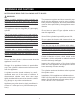
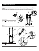
Step 5
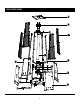
Attach the upper plate (#2) to the upper supports (#9) with (8) M5 x 12 screws (CC) as illustrated.
Step 6
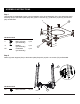
Attach the fire damper (#8) to the upper plate (#2) with (3) M5 bolts (FF) and (3) M5 nuts (DD), then attach
the reflector (#1) to the fire damper (#8) with (3) M5 wing nuts (AA) and (3) M5 studs (BB) as illustrated.
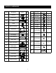
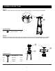
Hardware Used
M5 x 12 Screw
8 pcs
CC
Hardware Used
M5 Wing Nut
3 pcs
AA
M5 Stud
3 pcsBB
M5 Bolt
3 pcsFF
M5 Nut
3 pcsDD
1.
2.